GRUNDFOS INSTRUCTIONS SCALA1 SI Service instructions
English (GB) Service instructions . . . . . . . . . . . . . . . . . . . . . . . . . . . . . . . . . . . . . . . . . . . . . . . . . . . . . . . . . . . . . . . . . . . . . . . .
English (GB) English (GB) Service instructions Original service instructions Table of contents 1. 1.1 1.2 General information . . . . . . . . . . . . . . . . . . . . . . . . 4 Hazard statements . . . . . . . . . . . . . . . . . . . . . . . . . . 4 Notes . . . . . . . . . . . . . . . . . . . . . . . . . . . . . . . . . . 4 2. Safety information for working on the product . . . . . . . 4 3. Maintenance . . . . . . . . . . . . . . . . . . . . . . . . . . . . . 5 4. 4.1 4.2 4.3 4.4 4.5 4.6 4.7 4.8 4.
WARNING Moving parts Death or serious personal injury ‐ Make sure that the product cannot start unexpectedly while deblocking the pump shaft. WARNING Biological hazard Death or serious personal injury ‐ Before the pump is used for supplying drinking water, flush the pump thoroughly with clean water. The pump is maintenance-free, but we recommend that you check and clean the condensation plugs and integrated non-return valve once per year or as needed.
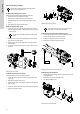
Position part numbers (numbers in brackets) refer to section SCALA1 exploded view. 174b 184a 4.1 Before dismantling the product 174c 184 1. Disconnect the power supply to the motor. 2. Remove power cable according to local regulations. 3. Gradually loosen the valves to release the pressure in the pump. 4. Remove the drain plug to drain the pump. 175 Tape the pressure switch to the side of the pump body while you continue the dismantling.
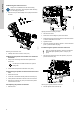
Remove the plug (169) on the nameplate to access the shaft end. 2. Find the locknut (67) at the non-drive end of the shaft. To remove the locking nut, place a 13-mm spanner on the nut and place the handle so that it rests against a flat surface to avoid spinning. 3. To loosen the shaft, use a large flat screwdriver at the driveend and, at the same time, hold the 13-mm spanner at the nondrive end. English (GB) 4.6 Removing the chamber stack 1.
Always use an antistatic service kit when handling electronic components. This will prevent static electricity from damaging components. 1. Remove the six pan-head Phillips screws (164a) that hold the the cover. TM075729 164a Opening lid and disconnecting the wires 164 TM075711 2. Disconnect the wires. 3. Remove the screw holding the printed circuit board. 4. Replace the printed circuit board. Make sure that the board fits on the four metal tabs in the corner. 5. Tighten the screw. 6.
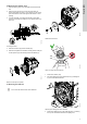
Note that the motor stool is on the outer end of the motor and the flange is on the inner end of the motor. 1. Loosen and remove the hex screws (152) that hold the motor stool (156b) to the outer end of the motor (150) using a size 10 hex key. English (GB) 5. Assembling the product 4.13 Removing the motor 5.1 Fitting the motor stool and the flange 1. Place the O-ring (150b) in the motor stool (156b). 2. Mount the motor (150) in the motor stool (156b). 3.
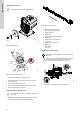
44a Do not touch the ceramic faces of the shaft seal. 67 66 44 4 45 49 45a 4a 4 45 49 45a 4a 4 45 49 4a 3 102 104 103 TM075701 45a Assembling the chamber stack a. Shaft seal, stationary part (103) b. Shaft seal, rotating part (104) c. Diffusor, final (3) d. Diffusor (4a) e. Backward bushing for impeller (45a) f. Impeller (49) 4 g. Forward bushing for impeller (45) TM076148 103 104 h. Chamber (4) i. Inlet part for hydraulic (44) j. Washer (66) Shaft seal and seal disc k. Lock nut (67) l.
English (GB) 5.6 Connecting the capacitor to the printed circuit board 1. Put the capacitor (161) inside the control box and connect it to the printed circuit board (181b). 26 26c TM075710 2 169 TM077548 Fitting the cover for hyraulic 5.10 Fitting the pressure switch 1. Prepare the O-ring (174b), the inductive sensor (174c) and the three screws (175) that hold the pressure switch onto the pump. 2. Place the O-ring (174b) on the pressure switch fitting. 3.
6.4 Type key for SCALA1 6.1 Lubricant Example: SCALA1 . 5- . 25 . 1x230V . 50 Hz . SCHUKO We recommend using soapy water for the shaft seal and ROCOL SAPPHIRE Aqua-Sil for the O-rings. Description 6.2 Torques Pos. Description Torque [Nm] 206 Screws that hold the flange (156a) to the 3.0 motor (150) 152 Screws for motor stool (156b) 3.5 26 Screws for connection module housing (2) 7.0 67 Lock nut for chamber 8.0 stack 6.
English (GB) TM075873 6.
English (GB) 164a 164 181a 181 150 181b 156a 161 181c 206 4 45 180 53 49 52 45a 4a 3 44a 102 67 66 104 169a 169 103 44 152 100 4 100b 45 37 49 45a 156b 4a 150b 4 65a 26 45 26c 49 65b 7 45a 11a 4a 403 41 174b 184 184a 43 174c 175 174a 2 178 177 116 11 10 SCALA1 3-35, 3-45, 5-55 exploded view 14 43a 178a 177a TM075294 100a
Estonia Lithuania South Africa Bombas GRUNDFOS de Argentina S.A. Ruta Panamericana km. 37.500 Centro Industrial Garin 1619 - Garín Pcia. de B.A. Tel.: +54-3327 414 444 Fax: +54-3327 45 3190 GRUNDFOS Pumps Eesti OÜ Peterburi tee 92G 11415 Tallinn Tel.: + 372 606 1690 Fax: + 372 606 1691 GRUNDFOS Pumps UAB Smolensko g. 6 LT-03201 Vilnius Tel.: + 370 52 395 430 Fax: + 370 52 395 431 Australia Finland Malaysia GRUNDFOS (PTY) LTD 16 Lascelles Drive, Meadowbrook Estate 1609 Germiston, Johannesburg Tel.
99830441 10.2020 Trademarks displayed in this material, including but not limited to Grundfos, the Grundfos logo and “be think innovate” are registered trademarks owned by The Grundfos Group. All rights reserved. ECM: 1298119 © 2020 Grundfos Holding A/S, all rights reserved.