
User Guide


6
English (US)
5. Installation
It is advisable that installation be carried out by
skilled personnel in possession of the technical
qualifications required by the specific legislation
in force.
The term skilled personnel means persons
whose training, experience and instruction, as
well as their knowledge of the respective
standards and requirements for accident
prevention and working conditions, have been
approved by the person in charge of plant
safety, authorizing them to perform all the
necessary activities, during which they are able
to recognize and avoid all dangers.
Use is allowed only if the electric system is in
possession of safety precautions in accordance
with the regulations in force in the country where
the product is installed.
5.1 Pre-installation checks
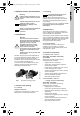
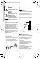
5.1.1 Checking motor shaft rotation
Before installing the pump, check that the
rotating parts turn freely:
1. Remove the fan cover from its seat in the
motor end cover.
2. Insert a screwdriver in the notch on the
motor shaft from the ventilation side.
3. If there is a blockage, turn the screwdriver,
tapping it gently with a hammer.
See fig. 3.
Fig. 3 Correcting blockage of motor shaft
rotation
5.2 Mechanical installation
5.2.1 Pump location
The pump must be located in a well-ventilated
place, protected from unfavorable weather
conditions and with an environmental
temperature not exceeding 104 °F (40 °C).
It is always good practice to place the pump as
close as possible to the liquid to be pumped.
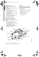
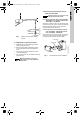
5.2.2 Pump position
The pump must be installed only in horizontal
position. To prevent movement and vibrations,
anchor the pump firmly to a horizontal surface.
See fig. 4.
Fig. 4 Anchor pump firmly in horizontal
position
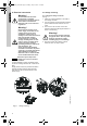
5.2.3 Pipework
Ensure that metal piping does not exert undue
strain on the connections, thus preventing
deformations or breakages.
The internal diameter of the pipework must
never be smaller than the diameter of the
suction port.
We recommend to fit a foot valve to the end of
the suction pipe.
For suction depths of over 13 ft or with long
horizontal stretches, it is advisable to use an
intake hose with a diameter larger than that of
the intake aperture of the pump.
To prevent the formation of air pockets, the
intake hose must slope slightly upward toward
the pump. See fig. 5.
If the intake pipe is made of rubber or flexible
material, always check that it is of the reinforced
type to avoid throttling due to suction.
The pipes must be adequately supported on
either side of the pump to avoid straining the
connections.
Warning!
All electrical work should be
performed by a qualified
electrician in accordance with the
latest edition of the National
Electrical Code, local codes and
regulations.
Warning!
Verify that the electrical supply
has been switched OFF before
making any connections.
The pump should not be
connected to the electrical
system until it has been properly
installed in the piping system.
Note
Reference Square D pressure
switch inner cover for electrical
schematic.
TM05 1171 2411
Note
Ensure that the maximum ambient
temperatures do not exceed
+104 °F (+40 C).
TM05 1173 2411
Note
Never use unnecessary force when
connecting the pipes.
JP_JP-PS_US.book Page 6 Tuesday, July 19, 2011 8:07 PM