
Product Overview
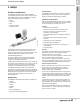
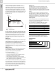
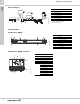
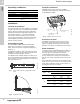
Table Of Contents
- 1. Grundfos DWS family
- 2. BMQE
- 3. MQ
- 4. JP Jet Pumps
- Product introduction
- Product overview
- Construction
- Operating conditions
- Selection
- Selection of pumps
- Installation
- Curve charts and technical data
- Dimensions and weights
- Cast iron shallow well, model JP05S-CI
- Cast iron shallow well, models JP15S-CI, JP20S-CI
- Cast iron shallow well, models JP30S-CI
- Shallow well stainless steel, model JP05S-SS
- Shallow well stainless steel, models JP07S-SS, JP10S-SS
- Cast iron deep well, models JP05D-CI, JP07D-CI
- Cast iron deep well, models JP15D-CI, JP20D-CI
- Electrical data
- Approvals
- 5. Further documentation

BMQE
Domestic water supply
2
6
If the consumption is suddenly changed — for
example, if a tap is opened — the water must start
flowing before the pressure can be made constant
again. Such dynamic variations depend on the pipe
work, but typically they will lie between 7 and 14 psi.
If the desired consumption is higher than the quantity
the pump is able to deliver at the desired pressure, the
pressure follows the pump curve as illustrated in the
far right of fig. 5.
Fig. 5 System function
At large flow rates, the pressure will drop quickly and
the pump will start immediately and maintain constant
pressure. When the system is running, the controller
makes small adjustments to the pressure to detect
whether there is consumption. If there is none, the
pump will simply refill the tank and stop after a few
seconds.
BMQE pump
The pumps used for BMQE system are modified SQE
submersible pumps. The BMQE pump is an SQE pump
with an MSE 3 motor. The pump and motor are
centered in the 4 inch stainless steel sleeve.
BMQE pumps are suitable for both continuous and
intermittent operation for a variety of pressure boosting
applications.
BMQE controller
The BMQE controller is a control and communication
unit specifically developed for the BMQE booster
pumps in constant pressure applications.
The controller provides:
• Full control of the BMQE pumps
• Two-way communication with the BMQE pumps
• Possibility of adjusting the pressure
• Alarm indication (LED) when service is needed
• The possibility of starting, stopping and resetting the
pump simply by means of a push-button.
The controller communicates with the pump via power
line communication, meaning that no extra cables are
required between the controller and the BMQE pump.
The controller incorporates external signal input for
pressure sensor and a pump status relay for use with
devices dependant on pump status.
BMQE motor
The MSE 3 motors are based on state-of-the-art
technology within permanent magnets (PM motor),
which accounts for the high motor efficiencies. In
addition, the motors have a built-in electronic unit with
a frequency converter for variable frequency and soft
starting.
The MSE 3 motors features high efficiency within a
wide load range. The high and flat efficiency curve of
the PM motor enables the same motor to cover a wide
power range as opposed to conventional AC motors.
For BMQE pumps, this means fewer motor variants.
Diaphragm tank
The pre-charge pressure of the diaphragm tank must
be set to 70 % of the pressure setting in order to use
the tank to the limit of its capacity.
Use the values in the following table. Pre-charge
pressure is measured with 0 psi in the pipeline.
Only a 2-gallon tank (Grundfos part number 91121984)
is recommended in the BMQE system. Use of a
different size tank will result in pressure fluctations.
Identification
Type key
TM04 9388 4010
Pressure
Flow
A
Stop
+7 PSI
Start
-7 PSI
Controlling
±3 PSI
Dynamic
variations
±7 PSI
GPM0.8
A = Pressure setting
Setting (psi) Pre-charge pressure (psi)
40 28
50 35
60 42
70 49
80 56
90 63
100 70
Example 22 BMQ E 05B 120
Rated flow [US gpm]
BMQE pump
Electronically controlled pump
via BMQE controller
Motor [Hp]
Head at rated flow [ft]