
Product Overview
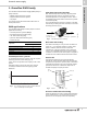
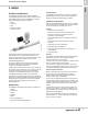
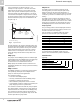
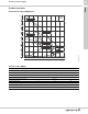
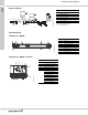
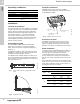
Table Of Contents
- 1. Grundfos DWS family
- 2. BMQE
- 3. MQ
- 4. JP Jet Pumps
- Product introduction
- Product overview
- Construction
- Operating conditions
- Selection
- Selection of pumps
- Installation
- Curve charts and technical data
- Dimensions and weights
- Cast iron shallow well, model JP05S-CI
- Cast iron shallow well, models JP15S-CI, JP20S-CI
- Cast iron shallow well, models JP30S-CI
- Shallow well stainless steel, model JP05S-SS
- Shallow well stainless steel, models JP07S-SS, JP10S-SS
- Cast iron deep well, models JP05D-CI, JP07D-CI
- Cast iron deep well, models JP15D-CI, JP20D-CI
- Electrical data
- Approvals
- 5. Further documentation

Grundfos DWS family
Domestic water supply
1
4
DWS product selection
Matching consumption and pump
capacity
Selecting the right pump is a matter of matching water
consumption with pump capacity. For best
performance, avoid installing an undersized or
oversized pump. Consumption may vary greatly
depending on housing standards and lifestyle. For
example, lawn sprinkler systems in the summer can
increase consumption.
Pump selection
Pump selection is based on the water demand and
required system head.
The water demand depends on the number of
consumers connected to the system.
Head can either be expressed in feet or psi. Head
refers to static head, pressure head, and friction head.
For assistance with pump selection, refer to the
WebCAPS product selection program; a link to CAPS
may be found on the Grundfos website.
Piping
In any water supply system, the sizing and choice of
materials of the pipework has an impact on the choice
of pumps and on the cost. Piping takes into account
the system head as referred to in Pump Selection.
Static head is the distance from the ground water level
to the uppermost tap. Pressure head is the system
pressure the user wants to achieve.
In most residential application this pressure is
approximately 60 psi. Friction head depends on the
pipe size, type and length.
When calculating friction loss remember to allow for
deterioration in the piping schematic, since all water
pipes will eventually become coated with rust, lime
deposits, etc.
Flow velocity in the piping must be kept low as noise
can occur due to turbulence in elbows and valves or
from water hammer.
Fitting a pressure relief valve in the discharge piping is
recommended to protect the piping from over-pressure
due to system malfunction.
Pressure tanks
A pressure tank should be installed in order to
minimize the number of pump starts and stops in the
water supply system, and to reduce problems with
water hammer in the pipework.
Tanks are included with the BMQE Constant Pressure
System and the MQ. The BMQE system has an
external tank. The MQ has an internal tank.
Jet pumps, however, may require the addition of a tank
depending upon the application.
Pressure switches
Pressure switches are used to control pump operation.
These switches have a cut-in pressure and a cut-out
pressure to turn the pump on and off.
The BMQE Constant Pressure System includes a
pressure transducer for constant pressure. The MQ
has a built-in pressure switch. Jet pumps have an
attached pressure switch.
Valves
Check valves
A check valve is a mechanical device which normally
allows fluid to flow through in only one direction.
The BMQE Constant Pressure System and the MQ
have built-in check valves. For suction lift applications
with the MQ, a check valve (provided) is required at
the inlet.
Foot Valves
A foot valve is required when pulling a suction lift
(shallow or deep well) with a Jet pump. This valve is
installed at the end of the suction pipe to prevent back
flow. The MQ will also benefit from the use of a foot
valve with suction lift applications.
Shut off valves
Shut off valves in the piping system make it possible to
drain only the part of the system that needs attention
or repair.
Flow control valves
Flow control valves are used in applications where a
set flow (gpm) is required; for example, a shower head
or an irrigation system.
Pressure reducing valves
Pressure reducing valves are used in applications
where the incoming water pressure exceeds the
maximum inlet pressure of the pump as is the case
with the MQ and city water pressure. The pressure
reducing valve (PRV) is used inline after the city water
tap and before the pump to ensure a set pressure.
Pressure relief valves
This valve is a spring controlled device that can be
adjusted to meet the needs of the pumping system.
Pressure relief valves are used in applications where
high pressure can result in damage to accessories; for
example, tanks with maximum pressure ratings.