
Product Overview
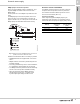
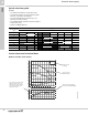
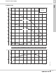
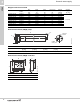
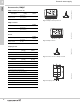
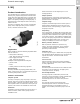
Table Of Contents
- 1. Grundfos DWS family
- 2. BMQE
- 3. MQ
- 4. JP Jet Pumps
- Product introduction
- Product overview
- Construction
- Operating conditions
- Selection
- Selection of pumps
- Installation
- Curve charts and technical data
- Dimensions and weights
- Cast iron shallow well, model JP05S-CI
- Cast iron shallow well, models JP15S-CI, JP20S-CI
- Cast iron shallow well, models JP30S-CI
- Shallow well stainless steel, model JP05S-SS
- Shallow well stainless steel, models JP07S-SS, JP10S-SS
- Cast iron deep well, models JP05D-CI, JP07D-CI
- Cast iron deep well, models JP15D-CI, JP20D-CI
- Electrical data
- Approvals
- 5. Further documentation

BMQE
Domestic water supply
2
11
BMQE pumps connected in parallel
When connecting BMQE pumps in parallel (fig. 10) a
separate BMQE controller must be used on each
BMQE pump.
Set the pressure on one BMQE 10 psi lower than the
other.
For BMQE pumps connected in parallel, mount one
above the other; it is recommended to connect the
pipes as shown in fig. 10. This layout ensures that the
BMQE pumps are filled with water before starting.
Fig. 10 Booster unit with two BMQE pumps connected in
parallel, mounted one above the other
Additional considerations when connecting in parallel:
• All BMQE modules are supplied with a non-return
valve.
• BMQE modules connected in parallel may also be
installed vertically.
• As venting problems may arise in such installations,
it is advisable to install suitable air vent devices.
• The BMQE should be positioned with the discharge
and air vent at the top when installed vertically.
• When the maximum flow for BMQE pumps in
parallel will exceed 35 gpm, a 4-gallon or two
2-gallon diaphragm tank(s) should be used.
Pressure sensor installation
The BMQE controller keeps the pressure constant in
the place where the pressure sensor is positioned.
The maximum shielded cable length for the sensor
must not exceed 1600 ft (487.7 m).
Generator operation
Power may be supplied to BMQE pumps by an
adequately sized generator. The generator must be
sized 50 % above the pumps P1 (input power) values.
TM04 9413 4110
Motor Hp
Minimum
generator size
[watts]
Recommended
generator output
[watts]
0.33 to 0.50 A 1100 1500
0.50 to 0.75 B 1700 2300
1.0 to 1.5 B 2000 3500