
Product Overview
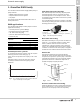
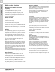
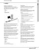
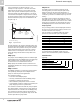
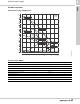
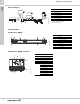
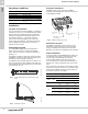
Table Of Contents
- 1. Grundfos DWS family
- 2. BMQE
- 3. MQ
- 4. JP Jet Pumps
- Product introduction
- Product overview
- Construction
- Operating conditions
- Selection
- Selection of pumps
- Installation
- Curve charts and technical data
- Dimensions and weights
- Cast iron shallow well, model JP05S-CI
- Cast iron shallow well, models JP15S-CI, JP20S-CI
- Cast iron shallow well, models JP30S-CI
- Shallow well stainless steel, model JP05S-SS
- Shallow well stainless steel, models JP07S-SS, JP10S-SS
- Cast iron deep well, models JP05D-CI, JP07D-CI
- Cast iron deep well, models JP15D-CI, JP20D-CI
- Electrical data
- Approvals
- 5. Further documentation

BMQE
Domestic water supply
2
10
Operating conditions
Installation
Location of installation
The sound pressure level of the BMQE is <74 db[A] at
a distance of 3 ft (1 m). It is recommended by Grundfos
that the pump be installed with sound and vibration
dampening equipment (flexible piping adapters and
anti-vibration mounting — not sold by Grundfos).
Like most mechanical equipment, this system can
create noises and vibrations. Grundfos recommends
that the BMQE pump should not be mounted in or
adjacent to living quarters.
Positioning the pump
The GRUNDFOS BMQE pump is supplied with a
built-in non-return valve. An arrow on the BMQE
sleeve shows the direction of liquid flow through the
pump (fig. 7).
The BMQE is suitable for both vertical and horizontal
installation; however, the discharge port should never
fall below the horizontal plane. See fig. 8.
The BMQE must be installed with the air relief vent in
the 12 o’clock position when installed horizontally and
when installed in the vertical position, the air vent must
be at the top of the unit.
Fig. 7 Arrow showing direction of liquid flow through
pump
Fig. 8 Installation positions
Controller installation
All BMQE pumps can be connected to BMQE
controllers. Each BMQE pump must be connected to
its own BMQE controller.
Fig. 9 BMQE controller entry ports
Connection of motor
The BMQE incorporates a starter device and can
therefore be connected directly to the main power
supply. The BMQE incorporates thermal overload
protection and requires no additional motor protection.
Cable installation
In situations where multiple BMQE power cables are
run parallel in wiring trays or conduit and less than
12 inches apart, the possibility for undesired
communication between units exists. When this
occurs, intermittent or continuous NO CONTACT is
typically seen. Other unexpected errors may also be
seen.
The chart shows single-phase 60 Hz maximum cable
length motor service to entrance. The maximum cable
length with one BMQE controller is 650 ft (198.1 m);
the maximum wire size is 10 AWG.
Flow: Max. 39 US gpm (8.9 m3/h)
Head: Max. 300 ft (91.4 m)
Liquid temperature: Max. 95°F (35°C)
Operating pressure: Max. 347 psi (23 bar)
Inlet pressure: Min. 8 psi (0.55 bar)
Sound-pressure level:
The sound pressure level of the BMQE
is lower than 74 db[A] at a distance of
3 ft (1 m).
TM04 9411 4110TM04 1375
TM01 7841 1511
Maximum cable length (one controller)
Motor rating Copper wire size (AWG)
Volts Hp
14 12 10
Maximum cable length [ft (m)]
115 0.50
100
(30.5)
160
(48.8)
250
(76.2)
230
0.50
400
(121.9)
650
(198.1)
650
(198.1)
0.75
300
(91.4)
480
(146.3)
650
(198.1)
1.0
250
(76.2)
400
(121.9)
630
(192)
Pressure sensor
entry
Power supply
entry
Submersible
drop cable entry