GRUNDFOS PRODUCT GUIDE Domestic water supply BMQE, MQ, Jets 60 Hz
Domestic water supply Table of contents 1. 2. 3. 4. 5.
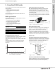
1 Domestic water supply DWS applications The Grundfos DWS family includes pumps to fit most applications including: • Constant pressure systems (BMQE) • flow-based pressure boosting (MQ) • rain water harvesting (MQ) • pressure-switch-based boosting (Jet) • suction lift (Jet). Flow-based pressure boosting With flow-based pressure boosting, the pump starts automatically when water is consumed and stops automatically when the consumption ceases.
1 Domestic water supply Grundfos DWS family DWS product selection Matching consumption and pump capacity Selecting the right pump is a matter of matching water consumption with pump capacity. For best performance, avoid installing an undersized or oversized pump. Consumption may vary greatly depending on housing standards and lifestyle. For example, lawn sprinkler systems in the summer can increase consumption. Pump selection Pump selection is based on the water demand and required system head.
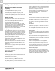
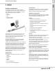
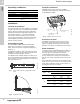
2 Domestic water supply BMQE 2. BMQE Product introduction Pumped liquids TM04 9387 4010 The BMQE Constant Pressure System maintains constant water pressure under varying demand, even with multiple taps running. The BMQE is a complete pressure boosting system that includes: • pump • controller • tank • mounting brackets • pressure sensor. Fig. 4 Grundfos BMQE Constant Pressure System High-quality construction and rugged design ensure low maintenance and trouble-free operation.
2 Domestic water supply BMQE If the consumption is suddenly changed — for example, if a tap is opened — the water must start flowing before the pressure can be made constant again. Such dynamic variations depend on the pipe work, but typically they will lie between 7 and 14 psi. If the desired consumption is higher than the quantity the pump is able to deliver at the desired pressure, the pressure follows the pump curve as illustrated in the far right of fig. 5.
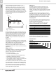
2 Domestic water supply BMQE Product overview Performance range, BMQE 60 Hz P [psi] H [ft] H [m] BMQE 60 Hz 15 BMQE 07B-180 120 280 80 240 100 200 60 22 BMQE 10C-190 80 15 BMQE 05A-110 160 60 40 120 22 BMQE 05B-120 40 80 30 BMQE 10C-130 22 BMQE 05A-80 20 20 0 0 TM05 0676 1411 30 BMQE 05B-90 40 0 0 0 5 1 10 2 15 3 20 4 25 5 30 6 35 7 8 Q [US GPM] 9 Q [m³/h] Product range, BMQE Range BMQE 15 3 Nominal flow rate [US gpm (m h)] 15 (3.4) BMQE 22 BMQE 30 22 (5.
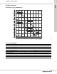
2 Domestic water supply TM04 9415 4110 BMQE System diagram Pos. Description 1 BMQE pump 2 BMQE controller 3 Diaphragm tank* 4 Pressure sensor 5 Mounting brackets 6 Flex connector** * Recommended size: 2 U.S. gal (8 liter) / 130 psi ** Not sold by Grundfos Construction Components, BMQE Pos. 8 4 5 1 2 7 3 TM05 0678 1411 6 Components, BMQE controller 6 1 Pos.
2 Domestic water supply BMQE Material specification Sleeve Pos. Description 90 Sleeve 91 92 Material 1a AISI Stainless steel 316 Flange Stainless steel 304 Cable entry Stainless steel/FKM 304 93 Air vent screw Stainless steel 304 94 O-ring FKM 70 14 39 14a 2 Pump Pos.
2 Domestic water supply BMQE Operating conditions Controller installation Flow: Max. 39 US gpm (8.9 m3/h) Head: Max. 300 ft (91.4 m) All BMQE pumps can be connected to BMQE controllers. Each BMQE pump must be connected to its own BMQE controller. Liquid temperature: Max. 95°F (35°C) Operating pressure: Max. 347 psi (23 bar) Inlet pressure: Min. 8 psi (0.55 bar) Sound-pressure level: The sound pressure level of the BMQE is lower than 74 db[A] at a distance of 3 ft (1 m).
2 BMQE pumps connected in parallel Pressure sensor installation When connecting BMQE pumps in parallel (fig. 10) a separate BMQE controller must be used on each BMQE pump. Set the pressure on one BMQE 10 psi lower than the other. For BMQE pumps connected in parallel, mount one above the other; it is recommended to connect the pipes as shown in fig. 10. This layout ensures that the BMQE pumps are filled with water before starting.
2 Domestic water supply BMQE Quick selection guide Example: • The maximum demand is 15 gpm (3.4 m3/h). • The pressure required is 70 psi (4.8 bar) system pressure at the taps in the building. • The normal minimum inlet pressure (e.g. city pressure) is 20 psi (1.4 bar) • The additional boost required is 50 psi (3.5 bar) at 15 gpm (3.4 m3/h). • Select a 15 BMQE 05A-110.
2 Domestic water supply P [psi] H [ft] BMQE 15 BMQE 60 Hz H [m] 15 BMQE 60 Hz 140 100 300 120 80 250 07B -180 (5-s tage) 100 200 60 80 150 05A -110 (3-s tage) 60 40 100 40 20 20 0 50 0 0 0 2 0. 0 P2 [kW] 4 0. 5 6 1. 0 8 1. 5 10 2. 0 12 2. 5 14 3. 0 16 3. 5 18 4. 0 Q [US GPM] 4. 5 Q [m³/h] P2 [hp] Et a [%] 0. 3 60 0. 2 P2 0. 2 40 0. 1 0. 1 20 0. 0 0.
2 Domestic water supply BMQE 22 BMQE 60 Hz P [psi] H [ft] H [m] 22 BMQE 60 Hz 140 100 300 120 80 250 100 200 10C -190 (5-s tage) 60 80 150 60 40 05B -120 (3stage) 100 40 05A -80 (2-stage) 20 20 0 50 0 0 0 5 0 P2 [kW] 1 10 2 15 3 20 4 25 5 30 6 Q [US GPM] 7 Q [m³/h] P2 [hp] Et a [%] 0. 6 60 0 0. 4 40 P2 0 0 0. 0 0 0 14 20 Et a 5 10 15 20 25 30 Q [US GPM] TM05 0773 1511 0.
2 Domestic water supply P [psi] H [ft] 30 BMQE 60 Hz 220 BMQE 30 BMQE 60 Hz H [m] 70 90 200 60 80 180 70 160 60 140 50 10C -130 (3-s tage) 40 120 50 100 05B -90 (2-stage) 30 40 80 30 20 60 20 40 10 10 0 20 0 0 0 5 0 P2 [kW] 1 10 2 15 3 20 4 25 5 30 6 35 7 8 Q [US GPM] 9 Q [m³/h] P2 [hp] Et a [%] 0. 6 60 0 P2 0. 4 40 0 0 20 Et a 0. 0 0 0 5 10 15 20 25 30 35 Q [US GPM] TM05 0774 1511 0.
2 Domestic water supply BMQE Weights and electrical data Product number Max. motor output [hp] Rated voltage [V] Rated current [A] Locked rotor current [A] Shipping weight [lb (kg)] 15 BMQE 05A-110 91128524 0.845 110-115 9.2 11.1 26 (11.8) 22 BMQE 05A-80 91128527 0.845 110-115 7.8 11.1 26 (11.8) 15 BMQE 05A-110 91128525 0.845 200-240 4.6 5.0 26 (11.8) 15 BMQE 07B-180 91128526 1.408 200-240 7.1 8.0 29 (13.2) 22 BMQE 05A-80 91128528 0.845 200-240 3.9 5.0 26 (11.
2 Domestic water supply Main power supply to pump 1 x 200-240 V –10 % / +6 %, 60 Hz 1 x 110-115 V –10 % / +6 %, 60 Hz Starting Soft starting. The motor starting current is equal to the highest value stated on the BMQE nameplate. Stopping Soft stopping when stopped by the BMQE controller Run-up time Maximum: 2 seconds. No limitation to the number of starts/stops per hour. Motor protection BMQE Technical data, BMQE pump Built into the pump.
2 Domestic water supply BMQE BMQE constant pressure kit Description BMQE controller and pressure sensor Rating Setting range 40 to 100 psi (2.8 to 6.9 bar) TM05 0732 / TM05 0733 BMQE Accessories, BMQE Product number 91128636 Fig. 11 BMQE constant pressure kit BMQE controller BMQE controller Rating Setting range 40 to 100 psi (2.8 to 6.9 bar) Product number 91121987 BMQE TM05 0732 1511 Description Sensor Description Pressure sensor for BMQE controller Rating 0 to 120 psi (0 to 8.
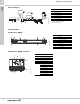
3 Domestic water supply MQ 3. MQ Product introduction Outlet connnection can be angled up to 5° to fit existing pipework. The Grundfos MQ is a compact pump and pressure boosting unit, purpose-designed for domestic water supply and other applications where a compact and reliable, easy-to-install pump is advantageous. The MQ is a self-priming multistage centrifugal pump; it self-primes from a well depth of down to 26 ft (8 m) within 5 minutes.
3 Domestic water supply MQ Identification Type key, MQ Example Pump range Rated flow [m3/h] Max.
3 Domestic water supply MQ Product overview Performance range, MQ 60 Hz H P [ft] [psi] 140 120 100 MQ 3 60 Hz 70 ISO 9906 Annex A -45 60 40 45 40 -35 50 35 30 40 25 80 60 50 30 20 20 15 20 10 0 0 10 5 0 2 0.0 0.5 4 6 1.0 8 1.5 10 2.0 12 2.5 14 3.0 16 3.5 Q [US GPM] 4.
3 Domestic water supply MQ Construction Components, MQ MQ control panel 1 3 1 2 4 9 5 8 6 3 6 4 5 TM05 0691 1411 7 Fig. 17 MQ control panel Pos. Description 1 Fig. 16 MQ pump components Power indicator light 2 Pos. 22 Description 1 Protective cover (accessory) 2 Discharge port 3 Suction port 4 Drain plug 5 Baseplate 6 Priming plug 7 Shaft access port plug 8 Pressure tank 9 Control panel TM05 0769 1511 2 Indicates the pump is ready for operation (green).
3 Domestic water supply Pos. Components MQ Material specification, MQ Material 2 Support flange PP + 30 % glass fiber 4 Chamber PPO + 20 % glass fiber 7 Drain and priming plug PPO + 20 % glass fiber 10 Self-priming valve PP + 30 % glass fiber 14 Self-priming part Pos. Pump sleeve Stainless steel, DIN W.-Nr. 1.
3 Domestic water supply MQ Operating conditions System pressure: Max. 109 psi (7.5 bar) Inlet pressure: Max. 40 psi (2.8 bar) Suction lift: Max. 26 ft (8 m) Liquid temperature: 32°F to +95°F (0°C to +35°C) Ambient temperature: 32°F to +113°F (0°C to +45°C) Installation Location The pump is suitable for indoor and outdoor installation. It is resistant to sunlight. For outdoor installation, the pump must be fitted with a protective cover (accessory).
3 Domestic water supply MQ Curve charts and technical data MQ 3-35 60 Hz, suction lift performance curve H [ft] P [psi] 110 48 MQ 3-35 34 46 60 Hz 32 100 H [m] 44 30 42 90 40 28 38 26 36 80 24 34 32 70 60 22 30 28 20 26 18 24 50 16 22 20 40 14 18 12 16 10 14 12 26.2 ft 10 20 23 ft 8 19.7 ft 13.1 ft 6.6 ft 8 6 6 10 4 0 ft 4 2 2 0 0 0 0 1 2 3 4 5 6 7 8 9 10 11 12 13 14 15 16 17 18 19 20 Q [US GPM] 0.0 0.5 1.0 1.5 2.0 2.5 3.0 3.
3 Domestic water supply H [ft] 140 130 120 110 100 90 80 70 60 50 40 30 20 10 0 P [psi] H [m] 64 62 60 58 56 54 52 50 48 46 44 42 40 38 36 34 32 30 28 26 24 22 20 18 16 14 12 10 8 6 4 2 0 MQ 3-45 44 60 Hz 42 40 38 36 34 32 30 28 26 24 22 20 18 16 14 12 10 26.2 ft 23 ft 19.7 ft 13.1 ft 8 6.6 ft 6 0 ft 2 0 0 1 2 3 4 5 6 7 8 9 10 11 12 13 14 15 16 17 18 19 20 21 22 Q [US GPM] 0.0 0.5 1.0 1.5 2.0 2.5 3.0 3.
3 Domestic water supply MQ Dimensional sketch - MQ D E H A TM01 9799 F B G C Dimensions [in (mm)] A B C D E F G H 9.45 (240) 2 x 3/8 (2 x 9.6) 22.44 (570) 7.56 (192) 12.60 (320) 4.49 (114) 8.58 (218) 12.74 (324) Weights and electrical data -10/+6 % voltage tolerance 7.5 ft. power cord with plug Part Number Phase, Volts MQ 3-35 96860172 MQ 3-45 Model Amps P2 Net wt. [lb (kg)] Run Start W Hp 1X110-120V 8 29 585 0.75 30.1 (13.
3 Domestic water supply MQ protective cover Protects keypad and electronics in outdoor applications. Required for outdoor applications where MQ is exposed to the elements. Two Velcro tabs are included to help adhere back end of cover to pump.
4 Domestic water supply Product introduction JP Jet Pumps 4. JP Jet Pumps • technopolymer impeller • convenient priming plug for ease of priming and air elimination • ceramic-carbon bellows mechanical seal ensures trouble-free operation • high quality pressure switch. The Grundfos JP line of self-priming centrifugal jet pumps is designed for shallow well, deep well, and convertible shallow well pump applications. JP pumps provide excellent suction capacity.
4 Domestic water supply JP Jet Pumps Identification Type key Example Jet pump Horsepower 03: 1/3 Hp 05: 1/2 Hp 07: 3/4 Hp 10: 1 Hp 15: 1-1/2 Hp 20 2 Hp 30: 3 Hp Well type S: Shallow Well D: Deep Well Material CI: Cast Iron SS: Stainless Steel EC: Engineered Composite 30 JP 05 S CI
4 Domestic water supply JP Jet Pumps Product overview Conversion chart Old JPF Shallow Well Cast Iron Jet Pumps Type Volts Pressure switch setting [psi] New Shallow Well Cast Iron Jet Pumps Material number Hp Ph Volts Pressure switch setting [psi] JP05S-CI (JP4-47ASA) 1/2 1 115/230 30-50 JP07S-CI (JP4-54ASA) 3/4 1 115/230 30-50 JP10S-CI (JP4-61ASA) 1 1 115/230 30-50 97855085 96430416 JP15S-CI (JP5-61ASA) 1-1/2 1 230 40-60 97855091 96457277 JP20S-CI (JP8-62ASA) 2 1 230
4 Domestic water supply JP Jet Pumps Performance range H [m] H [ft] JP 210 60 p [psi] 90 60 Hz 200 85 190 80 55 180 75 170 50 45 40 160 70 150 65 140 60 130 55 JP10 120 50 35 110 45 30 100 40 90 25 35 80 JP05 JP07 JP15 JP20 JP30 70 30 20 60 15 25 50 20 40 5 15 30 10 20 5 10 0 0 0 0 5 10 15 20 25 30 35 40 45 50 55 60 Q [US GPM] 0 32 2 4 6 8 10 12 Q [m³/h] TM05 1230 4511 10
4 Domestic water supply JP Jet Pumps Product range Shallow well Shallow well cast iron Shallow well stainless steel Model JP05S-CI 3 Max. flow [gpm (m h)] Max. pump head [ft (m)] JP07S-CI JP10S-CI JP30S-CI JP05S-SS JP07S-SS JP10S-SS 21 (4.7) 20 (4.5) 20 (4.5) 23 (5.2) 34 (7.7) 52 (11.8) 21 (4.7) 20 (4.5) 20 (4.5) 170 (51.2) 200 (61.0) 210 (64.0) 210 (64.0) 170 (51.2) 145 (44.2) 170 (51.2) 200 (61.
4 Domestic water supply JP Jet Pumps Construction Materials of construction Shallow well - cast iron, stainless steel 1 Descriptions: in contact with liquid 7 TM05 2216 4611 16 160 Pos.
4 Domestic water supply Max. operating pressure: Installation 116 psi (8 bar) Liquid temp range: JP Jet Pumps Operating conditions Pump location +32 °F to +95 °F (0 °C to +35 °C) Max. relative humidity of air 95% Storage temp range: +14 °F to +104 °F (-10 °C to 40 °C) Selection Pumped liquids JP pumps are suitable for pumping clean, non-viscous, non-aggressive, non-explosive liquids, free of solid particles or fibers.
4 Domestic water supply JP Jet Pumps Curve charts and technical data Performance curves Models JP05S-CI, JP05S-SS 45 H [ft] 150 QH 140 40 35 30 25 20 15 JP05 p [psi] 65 60 Hz 60 130 55 120 50 110 45 100 90 40 80 35 70 30 60 25 50 20 40 10 5 0 15 30 20 10 10 5 0 0 0 2 4 6 0.0 0.5 1.0 1.5 8 10 2.0 12 2.5 14 3.0 16 3.5 18 4.0 20 22 24 Q [US GPM] TM05 1137 5111 H [m] 4.
4 Domestic water supply H [m] H [ft] 60 200 p [psi] JP10 QH 60 Hz 180 50 80 160 70 140 60 40 120 30 JP Jet Pumps Models JP10S-CI, JP10S-SS 50 100 40 80 10 30 60 20 40 10 20 0 0 0 0 2 4 6 8 0.0 0.5 1.0 1.5 10 2.0 12 2.5 14 3.0 16 3.5 18 4.0 20 22 24 Q [US GPM] TM05 1141 5111 20 4.
4 Domestic water supply JP Jet Pumps Model JP20S-CI H [m] H [ft] p [psi] 220 60 50 40 30 JP20 QH 60 Hz 200 90 180 80 160 70 140 60 120 50 100 40 80 10 30 60 20 40 10 20 0 0 0 0 4 0 1 8 12 2 16 3 20 4 24 5 28 6 32 36 40 Q [US GPM] 7 TM05 1148 5111 20 Q [m³/h] Model JP30S-CI H [m] H [ft] p [psi] JP30 180 50 QH 160 70 140 60 40 120 30 80 60 Hz 50 100 40 80 10 30 60 20 40 10 20 0 38 0 0 0 4 0 1 8 2 12 16 20 24 28 32 36 40 44 48 52 56 Q [
4 Domestic water supply Pump type JP05S JP07S JP10S JP15S JP20S JP30S Part number cast iron 97855073 97855081 97855085 97855091 97855094 97855095 Part Pressure Suction number switch depth stainless setting [ft] steel on/off 97855075 97855083 97855088 - - - 30/50 30/50 30/50 40/60 40/60 40/60 Delivery pressure [psi] 15 20 25 30 35 40 45 50 55 60 65 Flow table [gpm] Max. pressure [psi] Shut off pressure [psi] 5 14.8 14.8 14.7 13.6 - - - - - - - 59 10 13.
4 Domestic water supply JP Jet Pumps Deep well performance data Delivery pressure [psi] Pump type Pump part number Ejector type NPT Ejector part number Pressure switch on/off Suction depth [ft] 20 30 40 50 60 70 80 90 Flow table [gpm] E 25 JP05D E 25 E 20 97855090 E 25 E 30 E 20 JP20D 97855093 E 25 E 30 40 96654384 96654383 30/50 30/50 97855080 E 30 JP15D 30/50 97855072 E 30 JP07D 96654383 96654384 96654382 96654383 96654384 96654382 96654383 96654384 30/50 40
4 Domestic water supply JP Jet Pumps Dimensions and weights Cast iron shallow well, model JP05S-CI A A1 C H3 H DNA DNM F B E TM05 2221 4611 ØI G Model JP05S-CI Dimensions [in] Part number A A1 B C E F G H H3 I DNA DNM Weight [lbs] 97855073 15.7 15.5 10.4 4.2 7.6 0.5 4.4 8.1 5.6 0.
4 Domestic water supply JP Jet Pumps Cast iron shallow well, models JP15S-CI, JP20S-CI A C H1 DNA H DNM TM05 2365 5011 B F E I G Dimensions [in] Part number A B C E F G H H1 I DNA DNM Weight [lbs] JP15S-CI 97855091 21.8 10.2 8.7 13.5 0.5 5.7 10 6.2 0.6 1.25 1 68 JP20S-CI 97855094 21.9 10.2 8.7 13.5 0.5 5.7 10 6.2 0.6 1.
4 Domestic water supply JP Jet Pumps Shallow well stainless steel, model JP05S-SS A C H3 H 1"NPT 1"NPT E F B TM05 2219 4611 ØI G JP05S-SS Dimensions [in] Part number A B C E F G H H3 I 97855075 16 10.4 4.7 8.1 0.6 4.4 8.3 5.6 0.4 Model Weight [lbs] 18 Shallow well stainless steel, models JP07S-SS, JP10S-SS A C H H2 H1 1"NPT 1"NPT F E B TM05 2220 4611 I G Dimensions [in] Part number A B C E F G H H1 H2 I Weight [lbs] JP07S-SS 97855083 16.8 10.
4 Domestic water supply JP Jet Pumps Cast iron deep well, models JP05D-CI, JP07D-CI A A1 C DNE H2 H1 H DNA DNM E F B TM05 2218 4611 ØI G Model Part number Dimensions [in] A A1 B C E F G H H1 H2 I DNA DNE DNM Weight [lbs] JP05D-CI 97855072 15 14.6 10.4 3.4 6.7 0.5 4.4 8.1 3.7 1.9 0.4 1.25 1 1 25 JP07D-CI 97855080 15.8 15.4 10.4 3.4 6.7 0.5 4.4 8.5 3.7 1.9 0.4 1.
4 Domestic water supply JP Jet Pumps Electrical data Supply voltage: 1 X 115/230V 60Hz 1 X 230V 60Hz Voltage tolerance + / - 6 % Electrical data 60 Hz Pump Model Part Number P2 Power Out [Hp] Service factor [Hp] Phase & voltage I [amps] Phase & voltage I [amps] Capacitor [uF] JP05D-CI 97855072 1/2 1.60 1x115 7.09 1x230 3.61 50 JP05S-CI 97855073 1/2 1.60 1x115 8.21 1x230 4.22 50 JP05S-SS 97855075 1/2 1.60 1x115 8.21 1x230 4.22 50 JP07D-CI 97855080 3/4 1.5 1x115 9.
5 Domestic water supply Further documentation 5. Further documentation WebCAPS WebCAPS is a Web-based Computer Aided Product Selection program available on www.grundfos.com. WebCAPS contains detailed information on more than 185,000 Grundfos products in more than 20 languages. In WebCAPS, all information is divided into 6 sections: • Catalog • Literature • Service • Sizing • Replacement • CAD drawings.
5 Sizing 0 Further documentation Domestic water supply 1 This section is based on different fields of application and installation examples, and gives easy step-by-step instructions in how to • select the most suitable and efficient pump for your installation • carry out advanced calculations based on energy consumption, payback periods, load profiles, life cycle costs, etc. • analyze your selected pump via the built-in life cycle cost tool • determine the flow velocity in wastewater applications, etc.
Being responsible is our foundation Thinking ahead makes it possible Innovation is the essence L-DWS-PG-01 0612 The name Grundfos, the Grundfos logo, and the payoff Be–Think–Innovate are registrated trademarks owned by Grundfos Management A/S or Grundfos A/S, Denmark. All rights reserved worldwide. ECM: - GRUNDFOS Pumps Corporation 17100 West 118th Terrace Olathe, Kansas 66061 Phone: +1-913-227-3400 Telefax: +1-913-227-3500 GRUNDFOS Canada Inc.