
Product Overview
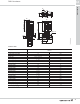
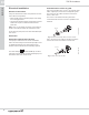
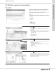
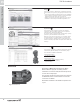
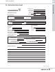
Table Of Contents
- Table of contents
- 1. Pump data
- 2. Performance range
- 3. Product range
- 4. Speed regulation
- 5. Operating condition
- 6. Pumped liquids
- 7. TP, TPE pumps
- 8. TPE Series 2000 pumps
- 9. TPE Series 1000 pumps
- 10. Communication
- 11. Motors
- 12. Curve charts
- 13. Installation
- 14. Accessories
- 15. Further documentation
- 16. Submittal data sheet

Installation
TPE E-circulators
13
43
Other connections TPE
See the wiring diagrams for instructions how to con-
nect external potential-free contacts for start/stop and
digital function, external setpoint signal and fault sig-
nal.
Connect the wires to the following terminal groups:
Note:
• As a precaution, separate the wires from each other
by reinforced insulation in their entire lengths.
• If no external on/off switch is connected, maintain
the connection across terminals 2 and 3.
Fig. 18 TPE wiring diagram
Group 1: Inputs (external start/stop, digital function,
setpoint and sensor signals, terminals 1-9
and bus connection, A, Y, B).
All inputs are separated from the mains
conducting parts by reinforced insulation.
Group 2: Output (signal relay).
The output, terminals C, NO and NC, are
galvanically separated from other circuits.
Therefore, the supply voltage or protective
extra-low voltage can be connected to the
output as desired.
Group 3: Mains supply.
TM02 0795 0904
0/1
10K
RUN
STOP
NC C NO N PE L
1987
65432
BYA
0-10 V
0/4-20 mA
4-20 mA
0/4-20 mA
0-10 V