
Install Instructions
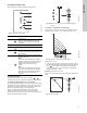
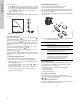
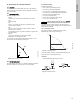
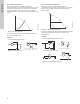
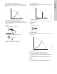
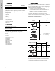
Table Of Contents
- English (US)
- 1. Limited warranty
- 2. Symbols used in this document
- 3. Abbreviations and definitions
- 4. General information
- 5. Mechanical installation
- 6. Electrical installation
- 7. Operating conditions
- 8. User interfaces
- 9. Standard control panel
- 10. Grundfos GO Remote
- 11. Description of selected functions
- 11.1 Setpoint
- 11.2 Operating mode
- 11.3 Set manual speed
- 11.4 Control mode
- 11.5 Analog inputs
- 11.6 Pt100/1000 inputs
- 11.7 Digital inputs
- 11.8 Digital inputs/outputs
- 11.9 Relay outputs
- 11.10 Analog output
- 11.11 Controller settings
- 11.12 Operating range
- 11.13 Setpoint influence
- 11.14 Monitoring functions
- 11.15 Special functions
- 11.16 Communication
- 11.17 General settings
- 12. Assist
- 13. Selection of control mode
- 14. Changing the position of the control panel
- 15. Bus signal
- 16. Priority of settings
- 17. Grundfos Eye
- 18. Signal relays
- 19. Megging
- 20. Technical data, single-phase motors
- 21. Technical data, three-phase motors
- 22. Inputs/outputs
- 23. Other technical data
- 24. Disposal
- Appendix

English (US)
18
Fig. 32 Constant level
11.4.7 Constant other value
Any other value is kept constant.
11.4.8 Constant curve
The pump can be set to operate according to a constant curve,
like an uncontrolled pump. See fig. 33.
The desired speed can be set in % of maximum speed in the
range from 25 to 100 % (110 %).
Fig. 33 Constant curve
11.5 Analog inputs
Available inputs depending on the functional module fitted in the
pump:
To set up an analog input, make the settings below.
Function
The analog inputs can be set to these functions:
• Not active
• Feedback sensor
• Ext. setpoint infl.
See section 11.13
Setpoint influence
.
• Other function.
Measured parameter
Select one of the parameters, i.e. the parameter to be measured
in the system by the sensor connected to the actual analog input.
Unit
Available measuring units:
Electrical signal
Select signal type (0.5 - 3.5 V, 0-5 V, 0-10 V, 0-20 mA or
4-20 mA).
Sensor range, min. value
Set the min. value of the connected sensor.
Sensor range, max. value
Set the max. value of the connected sensor.
11.6 Pt100/1000 inputs
Available inputs depending on the functional module fitted in the
pump:
Function
The Pt100/1000 inputs can be set to these functions:
• Not active
• Feedback sensor
• Ext. setpoint infl.
See section 11.13
Setpoint influence
.
• Other function.
Measured parameter
Select one of the parameters, i.e. the parameter to be measured
in the system.
Examples
• One external level sensor.
– emptying function.
• One external level sensor.
– filling function.
TM05 7957 1713
L
L
H
Q
Function (terminal)
FM 300
(advanced)
Analog input 1, setup (4) ●
Analog input 2, setup (7) ●
Analog input 3, setup (14) ●
Parameter Possible units
Pressure bar, m, kPa, psi, ft
Pump flow m
3
/h, l/s, yd
3
/h, gpm
Liquid temp. °C, °F
Other parameter %
Function (terminal)
FM 300
(advanced)
Pt100/1000 input 1, setup (17 and 18) ●
Pt100/1000 input 2, setup (18 and 19) ●