
Brochure

The name Grundfos, the Grundfos logo, and be think innovate are registered trademarks owned by Grundfos Holding A/S or Grundfos A/S, Denmark. All rights reserved worldwide. L-AL-SL-003 Rev. 08-17
www.grundfos.us
www.grundfos.ca
www.grundfos.mx
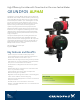
ALPHA1
Flow, Q: max. 21 gpm (80 lpm)
Head, H: max. 19 ft. (5.8 m )
Motor: 1 x 115V
Liquid temp.: 36°F to 230°F (2°C to 110°C)
Working Pressure: max. 150 PSI
Watts: 5-45 W
Amps: 0.65 A
Approvals: ETL, NSF 61, NSF 372
Canadian ICES-003
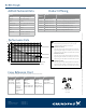
Product Offering
GRUNDFOS TACO B&G Armstrong WILO
UP 15-10F
UP 15-42F
UPS 15-42F
UPS 15-58FC
005-F2-3
006-F7
007-F5-5
008-F6-1
008-F6-3
00R-F6-1
00R-MSF
0015-MSF3-1
007e
0015e
NRF-9F/LW
NRF-22
NRF-25
NRF-9F/LW
Ecocirc 19-14 vario
Ecocirc 19-14 auto
Astro 20
Astro 25
Astro 30
Astro 230CI-R
Astro 250CI-R
Compass 20-20
Star S 16FX
Star S 21FX
Star S 21RFC
Stratos ECO 16 RFC
Grundfos
Buttereld Rd, Ste
Downers Grove, IL
Product
Number
Model Description
99287256 ALPHA1 15-55 F Cast iron ange with terminal box
99287259 ALPHA1 15-55 FR Cast iron rotated ange with terminal box
99287262 ALPHA1 15-55 SF Stainless ange with terminal box
99285998 ALPHA1 15-55 F/LC Cast iron ange with line cord
99287244 ALPHA1 15-55 FR/LC Cast iron rotated ange with line cord
99287250 ALPHA1 15-55 SF/LC Stainless ange with line cord
The Grundfos ALPHA1 can replace the pump models listed below:
Technical data
UP Series
6
65
ALPHA1
Performance and operating mode selection
The hydraulic performance shown is without check valve.
TM06 8910 1417
0 1 2 3 4 5 6 7 8 9 10 11 12 13 14 15 16
Q [US GPM]
0
2
4
6
8
10
12
14
16
18
20
[ft]
H
0
1
2
3
4
5
6
[m]
H
0.0 0.5 1.0 1.5 2.0 2.5 3.0 3.5 4.0
Q [m³/h]
Constant Pressure III
Constant Pressure II
Constant Pressure I
17 18
Pos. Description
• Push-button for selection of pump setting
• Every time the push-button is pressed, the circulator pump setting is changed.
III
Constant pressure III
• The duty point of the pump will move left and right along the highest constant-pressure curve depending on the water demand in the
system.
II
Constant pressure II
• The duty point of the pump will move left and right along the middle constant-pressure curve depending on the water demand in the
system.
I
Constant pressure I
• The duty point of the pump will move left and right along the lowest constant-pressure curve depending on the water demand in the
system.
UP_Series_US_1.fm Page 65 Thursday, July 27, 2017 8:33 PM
• Push-button for selection of pump setting
• Every time the push-button is pressed, the
circulator pump setting is changed.
Constant Pressure III
• The duty point of the pump will move left and
right along the highest constant-pressure curve
depending on the water demand in the system.
Constant Pressure II
• The duty point of the pump will move left and
right along the middle constant-pressure curve
depending on the water demand in the system.
Constant Pressure I
• The duty point of the pump will move left and
right along the lowest constant-pressure curve
depending on the water demand in the system.
ALPHA1 Technical Data
Performance Data
Cross Reference Chart
0 1 2 3 4 5 6 7 8 9 10 11 12 13 14 15 16
Q [US GPM]
0
2
4
6
8
10
12
14
16
18
20
[ft]
H
0
1
2
3
4
5
6
[m]
H
0.0 0.5 1.0 1.5 2.0 2.5 3.0 3.5 4.0
Q [m³/h]
Constant Pressure III
Constant Pressure II
Constant Pressure I
17 18
Drinking Water System Component
NSF / ANSI 61
NSF / ANSI 372