GRUNDFOS INSTRUCTIONS ALPHA2 Variable-speed circulators with AutoADAPT™ Installation and operating instructions Listed Conforms to ANSI/UL Std. 778 Certified to CAN/CSA Std. C22.2 No.
English (US) English (US) Installation and operating instructions Original installation and operating instructions These installation and operating instructions describe Grundfos ALPHA2. Sections 1-5 give the information necessary to be able to unpack, install and start up the product in a safe way. Sections 6-11 give important information about the product, as well as information on service, fault finding and disposal of the product. Prior to installation, read this document.
2. General information 2.1 Symbols used in this document DANGER Indicates a hazardous situation which, if not avoided, will result in death or serious personal injury. WARNING Indicates a hazardous situation which, if not avoided, could result in death or serious personal injury. CAUTION Indicates a hazardous situation which, if not avoided, could result in minor or moderate personal injury.
English (US) 3. Receiving the product 3.1 Inspecting the product Check that the product received is in accordance with the order. Check that the voltage and frequency of the product match voltage and frequency of the installation site. See section 7. Identification for information on the nameplate. 3.
When making pipe connections, follow the piping manufacturer's recommendations and all code requirements for the piping material. • Flush the system of debris before installation. • Insert the check valve if required. See fig. 1. • Refer to the arrows on the pump housing indicating the direction of the liquid flow through the pump. • Install the pump with horizontal motor shaft. See fig. 2. • Fit the two gaskets supplied to the pump ends. Check valve installation Fig.
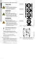
CAUTION Hot surface Minor or moderate personal injury. - Position the pump so that persons cannot accidentally come into contact with hot surfaces. Power head orientation A Power head orientation B DANGER Electric shock Death or serious personal injury. - Switch off the power supply before starting any work on the product. Make sure that the power supply cannot be accidentally switched on. Power head orientation C Pressurized system Death or serious personal injury.
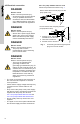
TM06 7711 3816 TM06 7589 4716 English (US) 4.4 Insulating the pump housing Insulating the pump housing TM06 7588 3516 Fig. 5 Limit the heat loss from the pump housing and pipes. Do not insulate the control box or cover the control panel. Fig. 6 Fitting insulating shells to the pump You can reduce the heat loss from the pump and pipes by insulating the pump housing and the pipes. See figures 5 and 6. • Insulating shells are supplied with ALPHA2 cast iron flanged versions. See fig. 6.
DANGER Electric shock Death or serious personal injury. - All electrical work must be carried out by a qualified electrician in accordance with the latest edition of the National Electric Code and state, local codes and regulations. DANGER Electric shock Death or serious personal injury. - Switch off the power supply before starting any work on the product. Make sure that the power supply cannot accidentally switched on. DANGER Electric shock Death or serious personal injury.
English (US) 4.5.2 For pump models with terminal box 1. Loosen the terminal box screw from the terminal box cover. 2. Utilize either conduit port for the wiring entrance. 3. Wirethe plug connector as illustrated in the section Wiring procedure below, steps 3a3d. Then complete steps 4-7. Be sure to connect the ground cable conductor (green) of the pump to the ground cable conductor of the power supply.
English (US) 5. Starting up the product Do not start the pump until the system has been filled with liquid and vented. The required minimum inlet pressure must be available at the pump inlet. 5.1 Venting the pump The pump is self-venting. It need not be vented before startup. The pump must not run dry. Air in the pump may cause noise. This noise ceases after a few minutes running. You obtain quick venting of the pump by setting the pump to speed III for a short period.
For information about pressures and temperatures, see section 10. Technical data. CAUTION Flammable material Minor or moderate personal injury. - Do not use the pump for flammable liquids, such as diesel oil and petrol. WARNING Biological hazard Death or serious personal injury. - In domestic hot-water systems, the temperature of the pumped liquid must always be above 122 °F (50 °C) due to the risk of legionella. WARNING Biological hazard Death or serious personal injury.
7.3 Approvals 7.1 Nameplate Listed TM04 3419 3516 English (US) 7. Identification Fig. 8 Pos. Nameplate Description 3191277 FCC sections Section 15.19 (a) 3 This device complies with Part 15 of the FCC Rules. Operation is subject to the following two conditions: (1) this device may not cause harmful interference, and (2) this device must accept any interference received, including interference that may cause undesired operation. 1 Product number 2 Voltage [V] 3 Rated current [A]: • Min.
TM04 3421 3511 8.1 Elements on the control panel Fig. 9 Control panel Pos. Description 1 Display showing the power consumption in watt or the flow. Light field indicating high and low flow 2 Production code: • 1st and 2nd figures: year • 3rd and 4th figures: week 3 Light field indicating fixed speed 4 Light field indicating constant pressure 5 Light field indicating AUTOADAPT 6 Push-button for selection of pump setting 8.
English (US) 8.5 Pump control See section 8.6 Pump performance and operating mode selection. AUTOADAPT, underfloor heating and two-pipe heating systems The AUTOADAPT function adjusts the pump performance to the actual heat demand in the system. As the performance is adjusted gradually, we recommend that you leave the pump in the AUTOADAPT mode at least one week before changing the pump setting.
English (US) 8.6 Pump performance and operating mode selection AUTOADAPT Operating range (maximum to minimum) Pos. TM06 7506 3516 The hydraulic performance shown is without check valve. Description • Push-button for selection of pump setting • Every time you press the push-button, the circulator setting is changed. III High constant speed • The pump runs at a constant speed and consequently on a constant curve. In speed III, the pump is set on the maximum curve under all operating conditions.
English (US) 9. Fault finding the product DANGER WARNING Electric shock Death or serious personal injury. - Switch off the power supply before starting any work on the product. Make sure that the power supply cannot be accidentally be switched on. Pressurized system Death or serious personal injury. - Before dismantling the pump, drain the system or close the isolating valve on either side of the pump before the screws are removed. The pumped liquid may be scalding hot and under high pressure.
Control panel 4. Light field is on. Insufficient heat English (US) Fault Remedy a) The pump performance is set too low. b) The thermostat is set too low or is not working. Check to see if the circulator is in the proper operating mode. Check the thermostat to ensure that it is set to the desired temperature and is working. Replace the batteries in the thermostat. c) Air or gas in the system. Vent the air or gas from the system by allowing the pump to run, as it will vent over time.
English (US) 10. Technical data In domestic hot water systems, keep the liquid temperature below 149 °F (65 °C) to eliminate the risk of lime precipitation. 10.1 Operating conditions Supply voltage 1 x 115 V, + 10 %/- 10 %, 60 Hz. Motor protection The pump requires no external motor protection. Enclosure class Indoor use only, IP42. CSA enclosure type 2. Watt readings Accuracy: ± 1 watt. Insulation class F.
English (US) 11. Disposing of the product This product or parts of it must be disposed of in an environmentally sound way: 1. Use the public or private waste collection service. 2. If this is not possible, contact the nearest Grundfos company or service workshop.
GRUNDFOS Canada GRUNDFOS México 9300 Loiret Blvd. Lenexa, Kansas 66219 Phone: (913) 227-3400 Fax: (913) 227-3500 2941 Brighton Road Oakville, Ontario L6H 6C9 Canada Phone: +1-905 829 9533 Telefax: +1-905 829 9512 Boulevard TLC No. 15 Parque Industrial Stiva Aeropuerto C.P. 66600 Apodaca, N.L. México Phone: 011-52-81-8144 4000 Fax: 011-52-81-8144 4010 www.grundfos.us www.grundfos.ca www.grundfos.
ECM: 1279905 www.grundfos.com Trademarks displayed in this material, including but not limited to Grundfos, the Grundfos logo and “be think innovate” are registered trademarks owned by The Grundfos Group. All rights reserved. 99187617 0220 © 2020 Grundfos Holding A/S, all rights reserved.