
Install Instructions

English (US)
8
7. Operating conditions
7.1 Maximum number of starts and stops
The number of starts and stops via the power supply must not
exceed four times per hour.
When switched on via the power supply, the pump will start after
approx. 5 seconds.
If a higher number of starts and stops is desired, use the digital
input for external start/stop when starting/stopping the pump.
When started via an external on/off digital input, the pump will
start immediately.
7.2 Ambient temperature
7.2.1 Ambient temperature during storage and transportation
Minimum -22 °F (-30 °C)
Maximum 140 °F (+60 °C).
7.2.2 Ambient temperature during operation
Minimum -4 °F (-20 °C)
Maximum 113 °F (+45 °C) (115 V models).
Maximum 122 °F (+50 °C) (220 V models)
The motor can operate with the rated power output (P2) at 122 °F
(50 °C), but continuous operation at higher temperatures will
reduce the expected product life. If the motor is to operate at
ambient temperatures between 122 °F and 140 °F (50 and 60
°C), an oversized motor must be selected. Contact Grundfos for
further information.
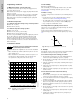
7.3 Installation altitude
Installation altitude is the height above sea level of the installation
site.
• Motors installed up to 3280 ft. (1000 meters) above sea level
can be loaded 100 %.
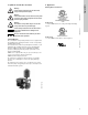
• Motors installed more than 3280 ft. (1000 meters) above sea
level must not be fully loaded due to the low density and
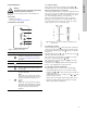
consequent low cooling effect of the air. See fig. 9.
Fig. 9 Derating of motor output power (P2) in relation to
altitude above sea level
7.4 Air humidity
Maximum air humidity: 95 %.
If the air humidity is constantly high and above 85 %, the drain
holes in the drive-end flange should be open. See section
5.5 Drain holes.
7.5 Motor cooling
To ensure cooling of motor and electronics, the following must be
observed:
• Position the motor in such a way that adequate cooling is
ensured. See section 5.3 Ensuring motor cooling.
• The temperature of the cooling air must not exceed 50 °C (122
°F) for 1x230V or 45 °C (113 °F) for 1x115V CMBE pumps.
• Keep cooling fins and fan blades clean.
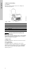
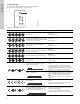
7.6 Pumps with factory-fitted pressure sensor
The pressure sensor is fitted on the pump discharge side, and the
pump is set to constant pressure.
In this control mode, the pump will adjust its performance, i.e.
pump discharge pressure, to the desired setpoint (H
set
). See fig.
10.
Fig. 10 Pump in constant-pressure control mode
8. Startup
After having carried out the mechanical and electrical installation
described in sections previously, proceed as follows:
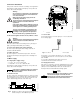
8.1 Positive inlet pressure start-up procedure
1. Check that the precharge pressure in the diaphragm tank is
0.7 times the required discharge pressure (setpoint).
2. Ensure all valves on discharge side and suction side of pump
are in open position.
3. Turn tap on discharge side of pump on allowing water to pass
through pump.
4. Turn power on to pump and press start/stop button on pump
to turn pump on.
5. Adjust the required setpoint pressure by using the up or down
arrows on motor.
8.2 Flooded suction and suction lift start up
procedures
1. Check that the precharge pressure in the diaphragm tank is
0.7 times the required discharge pressure (setpoint).
2. Use 10 mm allen wrench to remove vent plug on front of pump
just above suction port.
3. Use funnel and fill water into pump through vent port. When
water is no longer able to fill into pump, the pump is primed.
4. Reinstall vent plug. Be careful not to cross thread vent plug
while reinstalling.
5. Ensure all valves on discharge side and suction side of pump
are in open position
6. Turn power on to pump and press start/stop button on pump
to turn pump on.
7. 6. Adjust the required setpoint pressure by using the up or
down arrows on motor.
Caution
The motor must not be installed more than 6500
ft. (2000 meters) above sea level.
TM05 2863 0115
$OWLWXGH>IW@
3
>@
+
>
P
@
TM05 6398 4712
Q
H
H
set