
Use and Care Manual


English (GB)
4
3.5 Installation examples
Fittings, hoses and valves are not supplied with the pump.
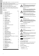
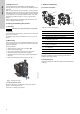
3.5.1 Mains water pressure boosting
Fig. 4 Mains water pressure boosting
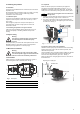
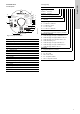
3.5.2 Suction from a well
Fig. 5 Suction from a well
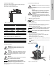
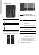
3.5.3 Suction from freshwater tank
Fig. 6 Suction from freshwater tank
TM06 4347 2015
Pos. Description
1 Highest tapping point
2 Pipe hangers and supports
3 Isolating valves
4 Flexible hoses
5 Bypass valve
6
Optional pressure-reducing valve on the inlet side if the
inlet pressure can exceed 10 bar (145 psi)
7
Optional pressure-relief valve on the outlet side if the
installation cannot stand up to a pressure of 6 bar (85
psi)
8
Drip tray. Install the pump on a small stand to avoid the
ventilation holes from being flooded.
9 Pressure gauge
10 Mains water pipe
TM06 4349 2015
Pos. Description
1 Highest tapping point
2 Isolating valve
3
Inlet filter.
If the water can contain sand, gravel or other debris,
please install a filter on the inlet side to protect the pump
and installation.
4 Foot valve with strainer
H1 Maximum suction lift is 8 m (29 ft)
49
1
37
2
5
10
6
2
3
8
H2 H1
4
3
2
1
H2 Inlet pipe must be submersed at least 0.5 m (1.64 ft)
TM06 4348 2015
Pos. Description
1 Highest tapping point
2 Pipe hangers
3 Isolating valve
4 Flexible hoses
5 Drain to sewer
6 Foot valve with strainer
7 Freshwater tank
Pos. Description
min1
1
2
3
4
7
6
5