
Use and Care Manual


English (GB)
3
3. Installing the product
3.1 Location
The pump can be installed indoors or outdoors, but it must not be
exposed to frost.
We recommend that you install the pump near a drain or in a drip
tray connected to a drain in order to lead away possible
condensation from cold surfaces.
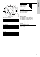
3.1.1 Minimum space
The pump can be installed in small spaces such as a cupboard. It
requires a minimum space of 430 x 215 x 325 mm (17 x 8.5 x
12.8 inches).
Even though the pump does not require much space, we
recommend that you leave enough space for service and
maintenance access.
3.1.2 Installing the product in frosty environment
If the pump is to be installed outdoors where frost may occur,
enclose it completely in insulating material to keep it from
freezing.
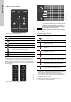
3.2 System sizing
The pump is factory-set to three bar outlet pressure which can be
adjusted according to the system in which it is incorporated.
The tank precharge pressure is 1.25 bar (18 psi).
3.3 Mechanical installation
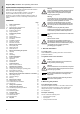
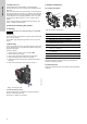
3.4 Foundation
Fasten the pump to a solid horizontal foundation by means of
screws through the holes in the base plate. See fig. 1.
Fig. 1 Base plate
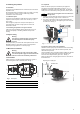
3.4.1 Pipework
Make sure that the pump is not stressed by the pipework.
The pumps are equipped with flexible connections, ± 5 °, to
facilitate the connection of inlet and outlet pipes. The inlet and
outlet ports can be loosened by turning the union nuts by hand.
1. Carefully screw the inlet and outlet connections on to the inlet
and outlet ports using a pipe wrench or similar tool.
2. Then fit the connections to the inlet and outlet holding the
connections with one hand, and tightening the union nuts with
the other hand. See fig. 2.
Fig. 2 How to fit the connections
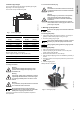
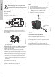
3.4.2 How to reduce noise in the installation
Vibrations from the pump may be transferred to the surrounding
structure and create noise in the 20-1000 Hz spectrum, also
called the bass spectrum.
Correct installation using a vibration-damping rubber pad, flexible
hoses and correctly placed pipe hangers for rigid pipes can
reduce the noise experienced by up to 50 %. See fig. 3.
Place pipe hangers for the rigid pipes close to the connection of
the flexible hose.
Fig. 3 How to reduce noise in the installation
Warning
The system in which the pump is incorporated
must be designed for the maximum pump
pressure.
Warning
Before starting any work on the product, make
sure that the power supply has been switched off
and that it cannot be accidentally switched on.
TM06 3809 1015
A 130 mm 5.12 inches
B 181 mm 7.13 inches
C 144 mm 5.67 inches
B
A
C
Caution
Always loosen and tighten inlet and outlet union
nuts by hand.
TM06 4318 1915
TM06 4321 1915
Rubber pad
Pipe hanger for rigid pipe
Flexible hose