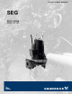
GRUNDFOS DATA BOOKLET SEG 2.0 to 5.
SEG Table of contents 1. 2. 3. 4. 5. 6. 7. 8. 9.
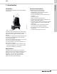
1 SEG Construction features This data booklet deals with Grundfos SEG sewage grinder pumps.
2 SEG Identification 2. Identification Type key The type key covers the entire range of Grundfos SEG sewage grinder pumps. Each SEG pump can be identified by means of the type key. Code Example SE Type range Grundfos sewage pumps G Impeller type Grinder system in the pump inlet [] Material Standard, cast iron [] Maximum spherical impeller clearance [mm] Not relevant for SEG pumps A15 A20 G Pump outlet Nominal diameter of pump outlet port = code number for type designation / 10 [inch] 1.
2 SEG Identification Nameplate The nameplate states the operating data and approvals applying to the pump. 2 3 4 5 ~ 6 7 8 9 10 11 12 ij 13 28 29 14 C Fig. 2 Pos. * 17 18 19 20 21 22 23 24 25 26 27 US TM06 5866 0216 15 16 1 SEG nameplate Description Pos.
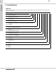
3 SEG Selection of product 3. Selection of product Ordering a pump Custom-built variants When ordering a pump, you need to take the following aspects into consideration: • pump type • custom-built variation (option) • accessories • controller • explosion-proof version. Pump type When you have selected the pump type, you can identify the specific pump that best meets your needs in sections Product range, page 9, and Type key, page 4.
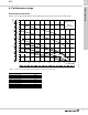
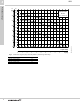
4 SEG Performance range 4. Performance range Performance overview Figures 3 and 4 show the performance range of SEG pumps. They give an overview of the various sizes. + >P@ + >IW@ 6(* $ +] +, % 5 5 5 5 Fig. 3 4 >86 *30@ 4 >O V@ TM05 8136 4715 Performance range for pumps with A15 [ANSI 1.
4 SEG Performance range + >P@ + >IW@ +] +, % 6(* $ Fig. 4 8 Performance range for pumps with A20 [ANSI 2.0" (DN 50 mm)] outlet flange Channel-impeller pumps Curve number SEG.A20.30.(EX).2.60H/M SEG.A20.40.(EX).2.60H/M SEG.A20.55.(EX)2.
5 SEG Product range 5. Product range Product range SEG pumps - A15 outlet flange Pump type SEG.A15.20.2.1.603 SEG.A15.20.R2.2.1.603 SEG.A15.20.R1.2.1.603 SEG.A15.20.2.60H SEG.A15.20.R2.2.60H SEG.A15.20.R1.2.60H SEG.A15.20.2.60L SEG.A15.20.2.60M SEG.A15.20.R2.2.60M SEG.A15.20.R1.2.60M SEG.A15.30.2.60H SEG.A15.30.2.60L SEG.A15.30.2.60M SEG.A15.40.2.60H SEG.A15.40.2.60L SEG.A15.40.2.60M SEG.A15.55.2.60H SEG.A15.55.2.60L SEG.A15.55.2.
5 SEG Product range SEG pumps - A20 outlet flange Pump type SEG.A20.30.2.60H SEG.A20.30.2.60L SEG.A20.30.2.60M SEG.A20.40.2.60H SEG.A20.40.2.60L SEG.A20.40.2.60M SEG.A20.55.2.60H SEG.A20.55.2.60L SEG.A20.55.2.
6 SEG Variants 6. Variants List of variants Motor Standard cables Cable B, 7G AWG16. Ex cables Cable B, 7B AWG16 Ex. Screened power cables for variable frequency drives Screened cable B. Cable protection Special motor For 7-core cable. Contact Grundfos.
7 SEG Construction 7. Construction Material specification, SEG pumps The position numbers in the table below refer to the sectional drawings and exploded views on the following pages. Pos. Description Material AISI/ASTM EN standard 6a Pin 7a Rivet Stainless steel 301 1.4310 Stainless steel A2/304 9a 1.4301 Key Stainless steel - - 37a O-rings NBR - - 44 Grinder ring Stainless steel 630 1.4542 45 Grinder head Stainless steel 630 1.
7 Construction SEG 190 188a 158 154 181 198 159 48 55 172 76 26a 150a 155 153 176 103 173 102 173a 48a 6a 193 37a 194 92 107 50 104 37 105a 105 107 58 49 Fig. 5 188a 68 45 188a 66 44 TM02 5378 2802 9a Sectional drawing of SEG pumps, 2.0 hp (1.
7 SEG Construction 181 198 26a 188a 66 176 188a 190 104 105a 173 173a 55 150a 7a 76 107 194 105 193 58 194 193a 188a 6a 49 48 159 48a 92 92 158 154 37 172 9a 50 37a 68 45 66 153 188a 102 103 Fig. 6 14 Exploded view of SEG pumps, 2.0 hp (1.
7 Construction SEG 190 188a 158 154 181 198 159 48 55 172 76 26a 150a 155 153 176 153a 173 173a 6a 193 37a 194 92 50 153b 105 37 107 58 102 49 Fig. 7 9a 68 45 188a 66 44 188a TM02 5408 2804 112a Sectional drawing of SEG pumps, 3.0 to 5.5 hp (2.6, 3.1 and 4.
7 SEG Construction 181 198 26a 188a 153a 66 176 173 173a 55 150a 7a 76 185 187 153b 188a 190 105 112a 194 107 193 58 194 193a 188a 6a 49 48 159 92 92 158 154 37 172 9a 50 37a 68 45 66 155 188a 153 188a 102 Fig. 8 16 Exploded view of SEG pumps, 3.0 to 5.5 hp (2.6, 3.1 and 4.
8 SEG Features Ball bearings The ball bearings are greased for life. Top bearings: • 2.0 hp (1.5 kW): Single-row ball bearing 6201. • 3.0 hp (2.6 kW) and up: Single-row ball bearing 6205. Bottom bearings: • 2.0 hp (1.5 kW): Single-row ball bearing 6303. • 3.0 hp (2.6 kW) and up: Angular-contact ball bearing 3205. Shaft seal The SEG range is available with two shaft seal variants. Both variants are fitted as cartridge seals. The shaft seal separates the motor from the pumped liquid. 2.0 hp (1.
8 SEG Product description Operating conditions Pumped liquids The pumps are designed for intermittent operation (S3). When completely submerged, the pumps can also operate continuously (S1). pH value: 4-10. Liquid temperature: 32-104 °F (0-40 °C). When pumping liquids with a density and/or a kinematic viscosity higher than that of water, use motors with correspondingly higher outputs. For short periods (maximum 3 minutes), temperatures up to 140 °F (60 °C) are permissible (non-Ex versions only).
8 SEG Product description Approvals The standard versions of SEG 60 Hz pumps have been approved by CSA, and the explosion-proof versions hold an FM type examination certificate. Approval standards These pumps are CSA approved according to UL778 and C22.2 no. 108, no. 0.4, no. 30, no. 145 and no. 60529. The pumps are FM approved according to FM 3600, FM 3615 and FM 3650 and ANSI/IEC 60529.
8 SEG 320 °F/ 275 °F (160 °C/ 135 °C 302 °F/ 257 °F (150 °C/ 125 °C) Wire No. Type Connection 1 Common (C) U1 / Z1 2 Run (R) U2 3 Start (S) Z2 TM06 5693 0316 Product description Wiring diagrams Fig. 12 Wiring diagram for single-phase SEG pumps See table below. SEG Cs starting capacitor [μF] 150 [V] 230 Cr run capacitor [μF] 30 [V] 450 338 °F 302 °F (170 °C) (150 °C) Fig.
9 SEG Curve charts 9. Curve charts How to read the performance curves The curves on the following pages apply to SEG pumps. SEG Page SEG.A15.20.2.1.603 SEG.A15.20.R2.2.1.603 SEG.A15.20.R1.2.1.603 SEG.A15.20.2.60H/L/M SEG.A15.20.R2.2.60H/L/M SEG.A15.20.R1.2.60H/L/M SEG.A15.30.2.60H/L/M SEG.A15.40.2.60H/L/M SEG.A15.55.2.60H/L/M SEG.A20.30.2.60H/L/M SEG.A20.40.2.60H/L/M SEG.A20.55.2.
9 SEG Curve charts Curve conditions Certificates The guidelines below apply to the curves on pages 23 to 34. • Tolerances are according to HI 11.6:2012 3B. • The curves show the pump performance with different impeller diameters at the rated speed. • The curves apply to the pumping of airless water at a temperature of 68 °F (20 °C) and a kinematic viscosity of 1 cSt (1 mm2/s). • The Eff curves show the efficiency of the pump for the different impeller diameters.
Performance curves and technical data 10 10. Performance curves and technical data SEG.A15.20.(EX).2.1.
10 + >P@ 3 >KS@ + >IW@ 6(* $ 5 +] +, % 4+ (II > @ (II (II 3 3 $16, ò '1 $16, '1 4 >86 *30@ 4 >O V@ TM06 1312 2214 Performance curves and technical data SEG.A15.20.R2.(EX).2.1.
Performance curves and technical data 10 SEG.A15.20.R1.(EX).2.1.
10 + >P@ 3 >KS@ + >IW@ 4+ 6(* $ +] +, % (II > @ 3 3 (II $16, '1 $16, ò '1 (II 4 >86 *30@ 4 >O V@ TM05 8127 0514 Performance curves and technical da
Performance curves and technical data 10 SEG.A15.20.R2.(EX).2.
10 + >P@ 3 >KS@ + >IW@ 6(* $ 5 + 0 +] +, % 4+ (II > @ 3 3 $16, '1 (II $16, ò '1 (II 4 >86 *30@ 4 >O V@ TM06 1315 2214 Performance curves and technical data SEG.A15.20.R1.(EX).2.
Performance curves and technical data 10 SEG.A15.30.(EX).2.
10 + >P@ 3 + >KS@ >IW@ 6(* $ 4+ +] +, % (II > @ (II 3 3 $16, ò '1 $16, '1 (II 4 >86 *30@ 4 >O V@ TM05 8129 0514 Performance curves and technical data SEG.A15.40.(EX).2.
Performance curves and technical data 10 SEG.A15.55.(EX).2.
10 + >P@ 3 >KS@ + >IW@ 3 3 6(* $ 4+ +] +, % (II > @ (II (II $16, '1 $16, ò '1 4 >86 *30@ 4 >O V@ TM05 8131 0514 Performance curves and technical data SEG.A20.30.(EX).2.
Performance curves and technical data 10 SEG.A20.40.(EX).2.
10 + >P@ 3 + >KS@ >IW@ 6(* $ +] +, % (II > @ 4+ (II $16, '1 $16, ò '1 3 4 >86 *30@ (II 3 4 >O V@ TM05 8133 0514 Performance curves and technical data SEG.A20.55.(EX).2.
11 SEG Dimensions and weights 11. Dimensions and weights TM06 5743 0116 SEG pumps Fig. 14 Installation on auto-coupling Power D F Z3 [hp (kW)] 2.0 (1-phase) (1.5) SEG.A15 2.0 (3-phase) (1.5) 3.0 (2.6) 4.0 and 5.5 (3.1 and 4.0) Power Z6 Z7 Z9 Z10a Z11 [in. (mm)] 8.5 (216) 8.5 (216) 10.08 (256) 10.08 (256) 4.53 (115) 4.53 (115) 4.53 (115) 4.53 (115) 4.65 (118) 4.65 (118) 4.65 (118) 4.65 (118) 16.57 (421) 16.57 (421) 18.19 (462) 18.19 (462) 14.61 (371) 14.61 (371) 16.22 (412) 16.
11 SEG Dimensions and weights SEG pumps OIL Fig. 15 Free-standing installation Power A [hp (kW)] SEG.A15 2.0 (1-phase) (1.5) 2.0 (3-phase) (1.5) 3.0 (2.6) 4.0 and 5.5 (3.1 and 4.0) Power 3.0 (2.6) 4.0 and 5.5 (3.1 and 4.0) Fig. 16 Free-standing installation with foot extensions C D SEG.A15.20... SEG.A15.30... SEG.A15.40.2.60H SEG.A15.40.2.60L SEG.A15.40.2.60M SEG.A15.55.2.60H SEG.A15.55.2.60L SEG.A15.55.2.60M Pumps, A20 outlet flange SEG.A20.30... SEG.A20.40... SEG.A20.55... 36 E F H 18.
12 SEG Accessories 12. Accessories Installation systems for SEG pumps 2 3 4 5 TM01 7173 1409 Description TM03 0716 0505 TM02 5980 4602 1 Product TM05 7683 1513 No Dimensions Product number SEG.A15 SEG.A20 6.
12 SEG Accessories SEG pumps Level controllers Grundfos offers a wide range of pump controllers to keep a watchful eye on liquid levels in the wastewater collecting tank, ensuring correct operation and protection of the pumps. Controller ranges: • Dedicated Controls, DC • SLC and DLC level controllers. The DLC is designed for two-pump installations and DC can operate up to six pumps in the same pit.
12 SEG Accessories SLC and DLC Features and benefits TM05 6609 5012 Control of one pump (SLC) or two pumps (DLC). • Automatic alternating operation of two pumps (DLC). • Automatic test run (prevents shaft seals from seizing up in the event of long periods of inactivity). • Automatic alarm resetting, if required. • Automatic restarting, if required. • Alarm outputs as NO and NC. Fig.
13 SEG Grundfos Product Center 13. Grundfos Product Center Grundfos Product Center is an online search and sizing tool to help you make the right choice. http://product-selection.grundfos.com SIZING enables you to size a pump based on entered data and selection choices. REPLACEMENT enables you to find a replacement product. Search results will include information on • the lowest purchase price • the lowest energy consumption • the lowest total life cycle cost.
13 SEG Grundfos Product Center Grundfos GO Mobile solution for professionals on the GO! Grundfos GO is the mobile tool box for professional users on the go. It is the most comprehensive platform for mobile pump control and pump selection including sizing, replacement and documentation. It offers intuitive, handheld assistance and access to Grundfos online tools, and it saves valuable time for reporting and data collection. GET IT ON Subject to alterations.
© Copyright Grundfos Holding A/S ECM: 1168641 GRUNDFOS Chicago 3905 Enterprise Court P.O. Box 6620 Aurora, IL 60598-0620 Phone: +1-630-236-5500 Fax: +1-630-236-5511 GRUNDFOS Kansas City 17100 West 118th Terrace Olathe, Kansas 66061 Phone: +1-913-227-3400 Fax: +1-913-227-3500 www.grundfos.us GRUNDFOS Canada 2941 Brighton Road Oakville, Ontario L6H 6C9 Canada Phone: +1-905 829 9533 Fax: +1-905 829 9512 www.grundfos.ca GRUNDFOS México Boulevard TLC No. 15 Parque Industrial Stiva Aeropuerto C.P.