
Install Instructions
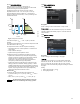
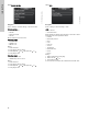
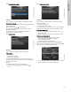
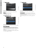
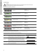
Table Of Contents
- English (US)
- 1. Limited warranty
- 2. Symbols used in this document
- 3. General information
- 4. Mechanical installation
- 5. Electrical installation
- 5.1 Supply voltage
- 5.2 Connection to the power supply (models 40-XX, 50-XX, 65-XX, 80-XX, 100-XX)
- 5.3 Connection to the power supply (models 32-XX)
- 5.4 Connection diagram
- 5.5 Input/output communication
- 5.6 Analog input for external sensor
- 5.7 Electrical connection for external sensor
- 5.8 Priority of settings
- 6. First start-up
- 7. Settings
- 8. Menu overview
- 9. Control panel
- 10. Menu structure
- 11. "Home" menu
- 12. "Status" menu
- 13. "Settings" menu
- 14. "Assist" menu
- 15. Selection of control mode
- 16. Fault finding
- 17. Sensor
- 18. Accessories
- 19. Technical data
- 20. Disposal
- Español (MX)
- 1. Garantía limitada
- 2. Símbolos utilizados en este documento
- 3. Información general
- 4. Instalación mecánica
- 5. Instalación eléctrica
- 5.1 Tensión de alimentación
- 5.2 Conexión al suministro eléctrico (modelos 40-XX, 50-XX, 65-XX, 80-XX y 100-XX)
- 5.3 Conexión al suministro eléctrico (modelos 32-XX)
- 5.4 Diagrama de conexiones
- 5.5 Comunicación de entrada/salida
- 5.6 Entrada analógica para sensor externo
- 5.7 Conexión eléctrica para sensor externo
- 5.8 Prioridad de los ajustes
- 6. Arranque inicial
- 7. Configurac.
- 8. Esquema de los menús
- 9. Panel de control
- 10. Estructura de los menús
- 11. Menú "Home"
- 12. Menú "Estado"
- 13. Menú "Configurac."
- 14. Menú "Assist"
- 15. Selección del modo de control
- 16. Localización de averías
- 17. Sensor
- 18. Accesorios
- 19. Datos técnicos
- 20. Eliminación
- Français (CA)
- 1. Garantie limitée
- 2. Symboles utilisés dans cette notice
- 3. Informations générales
- 4. Installation mécanique
- 5. Installation électrique
- 5.1 Tension d'alimentation
- 5.2 Branchement à l'alimentation électrique (modèles 40-XX, 50-XX, 65-XX, 80-XX, 100-XX)
- 5.3 Branchement à l'alimentation électrique (modèles 32-XX)
- 5.4 Diagramme de branchement
- 5.5 Communication entrée/sortie
- 5.6 Entrée analogique pour capteur externe
- 5.7 Branchement électrique pour capteur externe
- 5.8 Priorité des réglages
- 6. Première mise en marche
- 7. Réglages
- 8. Vue d'ensemble des menus
- 9. Panneau de commande
- 10. Structure des menus
- 11. Menu "Home"
- 12. Menu "Etat"
- 13. Menu "Réglages"
- 14. Menu "Assist"
- 15. Sélection du mode de régulation
- 16. Grille de dépannage
- 17. Capteur
- 18. Accessoires
- 19. Caractéristiques techniques
- 20. Mise au rebut

English (US)
36
15. Selection of control mode
System application
Select this control
mode
Recommended for most heating systems, especially in systems with relatively large pressure losses in the
distribution pipes. See description under proportional pressure.
In replacement situations where the proportional-pressure duty point is unknown.
The duty point has to be within the AUTO
ADAPT
operating range. During operation, the pump automatically
makes the necessary adjustment to the actual system characteristic.
This setting ensures minimum energy consumption and noise level from valves, which reduces operating costs
and increases comfort.
AUTO
ADAPT
The FLOW
ADAPT
control mode is a combination of AUTO
ADAPT
and FLOW
LIMIT
.
This control mode is suitable for systems where a maximum flow limit, FLOW
LIMIT
, is desired. The pump
continuously monitors and adjusts the flow, thus ensuring that the selected FLOW
LIMIT
is not exceeded.
Main pumps in boiler applications where a steady flow through the boiler is required. No extra energy is used for
pumping too much liquid into the system.
In systems with mixing loops, the control mode can be used to control the flow in each loop.
Benefits:
• Enough water for all loops at peak load conditions if each loop has been set to the right maximum flow.
• The dimensioned flow for each zone (required heat energy) is determined by the flow from the pump.
This value can be set precisely in the FLOW
ADAPT
control mode without the use of pump throttling valves.
• When the flow is set lower than the balancing valve setting, the pump will ramp down instead of losing energy
by pumping against a balancing valve.
• Cooling surfaces in air-conditioning systems can operate at high pressure and low flow.
FLOW
ADAPT
In systems with relatively large pressure losses in the distribution pipes and in air-conditioning and cooling systems.
• Two-pipe heating systems with thermostatic valves and
– a dimensioned pump head higher than 13 ft (4 meters)
– very long distribution pipes
– strongly throttled pipe balancing valves
– differential-pressure regulators
– large pressure losses in those parts of the system through which the total quantity of water flows (for
example boiler, heat exchanger and distribution pipe up to the first branching).
• Primary circuit pumps in systems with large pressure losses in the primary circuit.
• Air-conditioning systems with
– heat exchangers (fan coils)
– cooling ceilings
– cooling surfaces.
Proportional
pressure
In systems with relatively small pressure losses in the distribution pipes.
• Two-pipe heating systems with thermostatic valves and
– a dimensioned pump head lower than 6.5 ft (2 meters)
– dimensioned for natural circulation
– small pressure losses in those parts of the system through which the total quantity of water flows (for
example boiler, heat exchanger and distribution pipe up to the first branching) or
– modified to a high differential temperature between flow pipe and return pipe (for example district heating).
• Underfloor heating systems with thermostatic valves.
• One-pipe heating systems with thermostatic valves or pipe balancing valves.
• Primary circuit pumps in systems with small pressure losses in the primary circuit.
Constant pressure
H
Q
H
Q
H
Q
H
set
H
set
2
H
Q