
Install Instructions
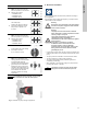
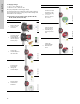
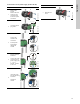
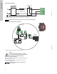
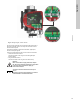
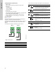
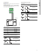
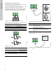
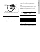
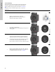
Table Of Contents
- English (US)
- 1. Limited warranty
- 2. Symbols used in this document
- 3. General information
- 4. Mechanical installation
- 5. Electrical installation
- 5.1 Supply voltage
- 5.2 Connection to the power supply (models 40-XX, 50-XX, 65-XX, 80-XX, 100-XX)
- 5.3 Connection to the power supply (models 32-XX)
- 5.4 Connection diagram
- 5.5 Input/output communication
- 5.6 Analog input for external sensor
- 5.7 Electrical connection for external sensor
- 5.8 Priority of settings
- 6. First start-up
- 7. Settings
- 8. Menu overview
- 9. Control panel
- 10. Menu structure
- 11. "Home" menu
- 12. "Status" menu
- 13. "Settings" menu
- 14. "Assist" menu
- 15. Selection of control mode
- 16. Fault finding
- 17. Sensor
- 18. Accessories
- 19. Technical data
- 20. Disposal
- Español (MX)
- 1. Garantía limitada
- 2. Símbolos utilizados en este documento
- 3. Información general
- 4. Instalación mecánica
- 5. Instalación eléctrica
- 5.1 Tensión de alimentación
- 5.2 Conexión al suministro eléctrico (modelos 40-XX, 50-XX, 65-XX, 80-XX y 100-XX)
- 5.3 Conexión al suministro eléctrico (modelos 32-XX)
- 5.4 Diagrama de conexiones
- 5.5 Comunicación de entrada/salida
- 5.6 Entrada analógica para sensor externo
- 5.7 Conexión eléctrica para sensor externo
- 5.8 Prioridad de los ajustes
- 6. Arranque inicial
- 7. Configurac.
- 8. Esquema de los menús
- 9. Panel de control
- 10. Estructura de los menús
- 11. Menú "Home"
- 12. Menú "Estado"
- 13. Menú "Configurac."
- 14. Menú "Assist"
- 15. Selección del modo de control
- 16. Localización de averías
- 17. Sensor
- 18. Accesorios
- 19. Datos técnicos
- 20. Eliminación
- Français (CA)
- 1. Garantie limitée
- 2. Symboles utilisés dans cette notice
- 3. Informations générales
- 4. Installation mécanique
- 5. Installation électrique
- 5.1 Tension d'alimentation
- 5.2 Branchement à l'alimentation électrique (modèles 40-XX, 50-XX, 65-XX, 80-XX, 100-XX)
- 5.3 Branchement à l'alimentation électrique (modèles 32-XX)
- 5.4 Diagramme de branchement
- 5.5 Communication entrée/sortie
- 5.6 Entrée analogique pour capteur externe
- 5.7 Branchement électrique pour capteur externe
- 5.8 Priorité des réglages
- 6. Première mise en marche
- 7. Réglages
- 8. Vue d'ensemble des menus
- 9. Panneau de commande
- 10. Structure des menus
- 11. Menu "Home"
- 12. Menu "Etat"
- 13. Menu "Réglages"
- 14. Menu "Assist"
- 15. Sélection du mode de régulation
- 16. Grille de dépannage
- 17. Capteur
- 18. Accessoires
- 19. Caractéristiques techniques
- 20. Mise au rebut

English (US)
16
5.5 Input/output communication
• Relay outputs
Alarm, ready and operating indication via signal relay.
• Digital input
– Start/Stop (S/S)
– Min. curve (MI)
– Max. curve (MA).
• Analog input
0-10 V or 4-20 mA control signal.
To be used for external control of the pump or as sensor input
for the control of the external setpoint.
The 24 V supply from pump to sensor is optional and is
normally used when an external supply is not available.
5.5.1 Relay outputs
See fig. 15, pos. 1.
The pump incorporates two signal relays with a potential-free
changeover contact for external fault indication.
The function of the signal relay can be set to "Alarm", "Ready" or
"Operation" on the pump control panel or with Grundfos GO
Remote.
The relays can be used for outputs up to 250 V and 2 A.
Fig. 17 Relay output
The functions of the signal relays appear from the table below:
TM05 3338 1212
Contact symbol Function
NC Normally closed
NO Normally open
C Common
NC NO C NC NO C
Alarm
Operation
Relay 1 Relay 2
Signal relay Alarm signal
Not activated:
• The power supply has been switched off.
• The pump has not registered a fault.
Activated:
• The pump has registered a fault.
Signal relay Ready signal
Not activated:
• The pump has registered a fault and is
unable to run.
Activated:
• The pump has been set to stop, but is ready
to run.
• The pump is running.
Signal relay Operating signal
Not activated:
• The pump is not running.
Activated:
• The pump is running.
132
NC NO C
132
NC NO C
12 3
NC NO C
132
NC NO C
132
NC NO C
12 3
NC NO C
132
NC NO C
132
NC NO C
12 3
NC NO C