
Install Instructions
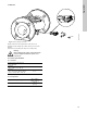
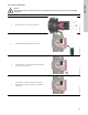


Table Of Contents
- English (US)
- 1. Limited warranty
- 2. Symbols used in this document
- 3. General information
- 4. Mechanical installation
- 5. Electrical installation
- 6. First start-up
- 7. Settings
- 8. Menu overview
- 9. Control panel
- 10. Menu structure
- 11. "Home" menu
- 12. "Status" menu
- 13. "Settings" menu
- 14. "Assist" menu
- 15. Selection of control mode
- 16. Fault finding
- 17. Sensor
- 18. Accessories
- 19. Technical data
- 20. Disposal

33
English (US)
17. Sensor
Fig. 34 Correct position of sensor
During maintenance and replacement of the sensor, it is
important that the sealing cap is fitted correctly on the sensor
housing.
Tighten the screw holding the clamp to 3.7 ft-lbs (5 Nm).
17.1 Sensor specifications
17.1.1 Pressure
* Full scale.
17.1.2 Temperature
TM05 3036 0812
Nose downwards
5 Nm
Warning
Before replacing the sensor, make sure that the
pump is stopped and that the system is not
pressurized.
Maximum differential pressure
during operation
29 psi / 2 bar / 0.2 MPa
Accuracy
+32 to +185 °F (0 to +85 °C)
2 % *
Accuracy
+14 to +32 °F and +185 to +266 °F
(-10 to 0 °C and +85 to +130 °C)
3 % *
Temperature range during operation
+14 to +266 °F
(-10 to +130 °C)
Accuracy
± 5.6 °F
(± 2 °C)