
Install Instructions
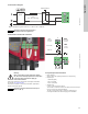

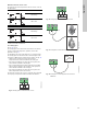
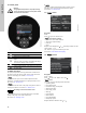
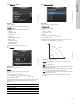
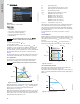
Table Of Contents
- English (US)
- 1. Limited warranty
- 2. Symbols used in this document
- 3. General information
- 4. Mechanical installation
- 5. Electrical installation
- 6. First start-up
- 7. Settings
- 8. Menu overview
- 9. Control panel
- 10. Menu structure
- 11. "Home" menu
- 12. "Status" menu
- 13. "Settings" menu
- 14. "Assist" menu
- 15. Selection of control mode
- 16. Fault finding
- 17. Sensor
- 18. Accessories
- 19. Technical data
- 20. Disposal

11
English (US)
5.3 Connection diagram
Fig. 11 Example of typical connection, 1 x 230 V ± 10 %, 50/60 Hz
5.4 Connection to external controllers
Fig. 12 Connection diagram
Concerning demands on signal wires and signal transmitters,
see section 19. Technical data.
Use screened cables for external on/off switch, digital input,
sensor and setpoint signals.
5.5 Input/output communication
• Relay outputs
Alarm, ready and operating indication via signal relay.
• Digital input
– Start/Stop (S/S)
– Min. curve (MI)
– Max. curve (MA).
• Analog input
0-10 V or 4-20 mA control signal.
To be used for external control of the pump or as sensor input
for the control of the external setpoint.
The 24 V supply from pump to sensor is optional and is
normally used when an external supply is not available.
TM03 2397 0312
External switch
Fuse
(min. 10 A, time lag)
ELCB
Note
Note
All cables used must be connected in
accordance with local regulations.
TM05 2901 1912 - TM05 3343 1212
Max.
250 V AC
2 A AC1
Min.
5 V DC
20 mA
Max.
24 V DC
22 mA
0-10 V DC
4-20 mA
I
NC NO C
S/S
M
I
M
A
IN
24V
Vcc
Signal
Vcc
Signal
3
2
1
Warning
Wires connected to supply terminals, outputs
NC, NO, C and start/stop input must be separated
from each other and from the supply by
reinforced insulation.
Note
Note
All cables used must be heat-resistant up to
+185 °F (+85 °C).