GRUNDFOS DATA BOOKLET MAGNA3 Circulator pumps 50/60 Hz
MAGNA3 Table of contents 1. 2. 3. Product description 3 Main applications 3 Type key 4 Product range 4 Performance range, MAGNA3 5 Performance range, MAGNA3 D single-head operation 6 Performance range, MAGNA3 D twin-head operation 7 Pump selection 8 Operating modes 11 Control modes 11 Additional features for control modes 14 Additional operating modes for multi-pump setup 16 Readings and settings on the pump 16 Communication 19 4. 5. 6. 7.
MAGNA3 1 The Grundfos MAGNA3 circulator pumps are designed for circulating liquids in the following systems: • heating systems • air-conditioning and cooling systems • domestic hot-water systems. • ground source heat pump systems • solar-heating systems. Duty range MAGNA3 (N) Single-head pumps Data Maximum flow rate, Q Maximum head, H Maximum system pressure Liquid temperature MAGNA3 D Twin-head pumps 570 GPM 346 GPM [150 m3/h] [78.5 m 3/h] 60 ft [18 m] 175 PSI [1.
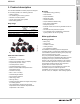
MAGNA3 2 Type key 2. Type key Code Example MAGNA3 (D) 100 -120 (F) (N) Type range MAGNA3 D Single-head pump Twin-head pump Nominal diameter (DN) of suction and discharge ports [mm] Maximum head [dm] F Pipe connection Flange N Pump housing material Cast iron Stainless steel Port-to-port length [mm] 3.
Fig.
Fig.
Fig.
MAGNA3 3 Product range Pump selection Frequently, pumps are selected based on a maximum flow and pressure loss in a system as well as peak efficiency of the pump. For circulators in variable demand systems such as a heating system where the heat load varies with the season and time of day it is more optimal to select a pump for this varying demand rather than one specific duty point. The MAGNA3 has been optimized for variable demand systems.
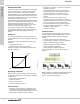
MAGNA3 3 System application Recommended for most heating systems, especially in systems with relatively large pressure losses in the distribution pipes. See description under proportional pressure. In replacement situations where the proportional-pressure duty point is unknown. The duty point has to be within the AUTOADAPT operating range. During operation, the pump automatically makes the necessary adjustment to the actual system characteristic.
MAGNA3 3 Product range System application If an external controller is installed, the pump is able to change from one constant curve to another, depending on the value of the external signal. The pump can also be set to operate according to the max. or min. curve, like an uncontrolled pump: • The max. curve mode can be used in periods in which a maximum flow is required. This operating mode is for instance suitable for hot-water priority. • The min.
MAGNA3 3 Operating modes Recommended for most heating systems. During operation, the pump automatically makes the necessary adjustment to the actual system characteristic. This setting ensures minimum energy consumption and noise level from valves, which reduces operating costs and increases comfort. Min. Q TM05 2446 5111 Max. H Normal: The pump runs according to the selected control mode. Note: The control mode and setpoint can be selected even if the pump is not running in "Normal" mode.
MAGNA3 3 Product range FLOWADAPT Proportional pressure The typical pump selection is based on required flow and calculated pressure losses. Pumps are often oversized. To adjust for "oversized" pumps, valves are typically used to increase the resistance and thus reduce the flow. The FLOWADAPT function reduces the need for a pump throttling valve. Note: This function cannot eliminate the need for balancing valves in heating systems.
MAGNA3 Constant temperature Differential Temperature In heating systems with a fixed system characteristic, for example domestic hot-water systems, the control of the pump according to a constant return-pipe temperature is relevant. This control mode ensures a constant differential temperature drop across a heating system. The pump should be installed in the flow pipe so the built-in sensor measures the fluid temperature going out to the load.
MAGNA3 3 The pump can be set to operate according to a constant curve, like an uncontrolled pump. See fig. 18. The desired speed can be set in % of maximum speed in the range from 25 to 100 %. H Normal proportional-pressure duty point FLOWLIMIT duty point Hset H Hset 2 Q TM05 2543 0412 Product range Constant curve Fig. 18 Constant-curve duty H Hset Normal constant-pressure duty point FLOWLIMIT duty point The pump can also be set to operate according to a selected curve.
MAGNA3 3 Product range Setting values for control modes (Single-head operation) The setting values for FLOWADAPT and FLOWLIMIT are indicated as percent of Qmax, Pump type AUTOADAPT Hfac ft [m] MAGNA3 MAGNA3 MAGNA3 MAGNA3 MAGNA3 MAGNA3 MAGNA3 MAGNA3 MAGNA3 40-80 F (N) 40-120 F (N) 40-180 F (N) 50-80 F (N) 50-150 F (N) 65-120 F (N) (D) 65-150 F (N)* (D) 80-100 F (N)* (D) 100-120 F (N)* 14.8 21.3 31.2 14.8 26.2 21.3 26.2 18.0 21.3 [4.5] [6.5] [9.5] [4.5] [8.0] [6.5] [8.0] [5.5] [6.
MAGNA3 3 Product range Additional operating modes for multi-pump setup Multi-pump function The multi-pump function enables the control of single-head pumps connected in parallel and twin-head pumps without the use of external controllers. The pumps in a multi-pump system communicate with each other via the wireless GENIair connection. A multi-pump system is set up via a selected pump, i.e. the master pump (first selected pump). The multi-pump functions are described in the following sections.
MAGNA3 Factory setting "Status" menu The pumps have been factory-set to AUTOADAPT without Automatic Night Setback. This menu shows the status of the pump and system as well as warnings and alarms. Note: No settings can be made in this menu. This menu offers the following: • Operating status • Pump performance • Power and energy consumption • Warning and alarm • Heat energy meter • Work log • Fitted modules • Date and time • Pump identification • Multi-pump system.
MAGNA3 3 Heat energy meter The "Assist" menu guides the user through the setting of the pump. In each submenu, the user is presented with a guide that assists throughout the setting. This menu offers the following: • Step-by-step instructions in how to set up the pump. • A short description of the six control modes and recommended applications. • Assistance in fault correction.
MAGNA3 Grundfos Eye Communication The Grundfos Eye at the top of the control panel is a pump status indicator light providing information about the pump operating status. The indicator light will flash in different sequences and provide information about the following: • power on/off • pump warnings • pump alarms • remote control. The function of the Grundfos Eye is described in detail in the installation and operating instructions.
MAGNA3 3 Product range Wireless GENIair The pump is designed for multi-pump connection via the wireless GENIair connection. The built-in wireless GENIair module enables communication between pumps and with the Grundfos GO Remote without the use of add-on modules. • Multi-pump function. See section Multi-pump function. • Grundfos GO Remote. See section Grundfos GO Remote. TM05 3811 1612 CIM modules Fig. 32 Grundfos CIM modules A CIM module is an add-on Communication Interface Module.
MAGNA3 3 Module Fieldbus protocol Description Functions GENIbus The CIM 050 is a Grundfos communication interface module used for communication with a GENIbus network. The CIM 050 has terminals for the GENIbus connection. The CIM 100 is a Grundfos communication interface module used for communication with a LonWorks network. The CIM 100 has terminals for the LonWorks connection. Two LEDs are used to indicate the actual status of the CIM 100 communication.
MAGNA3 4 Operating conditions 4.
MAGNA3 4 The MAGNA3 incorporates a differential-pressure and temperature sensor. The sensor is located in the pump housing in a channel between the suction and discharge ports. The sensors of twin-head pumps are connected to the same channel and the pumps therefore register the same differential pressure and temperature. Via a cable, the sensor sends an electrical signal for the differential pressure across the pump and for the liquid temperature to the controller in the control box.
MAGNA3 5 Construction 5. Construction The MAGNA3 is of the canned-rotor type, i.e. pump and motor form an integral unit without shaft seal and with only two gaskets for sealing. The bearings are lubricated by the pumped liquid.
MAGNA3 5 TM05 2319 0312 Construction Sectional drawing Fig. 33 MAGNA3 Material specification Pos.
MAGNA3 6 Installation 6. Installation Mechanical installation Insulating shells The MAGNA3 is designed for indoor installation. The pump must be installed with horizontal motor shaft. The pump may be installed in horizontal as well as vertical pipes. The insulating shells supplied with single-head MAGNA3 pumps are for heating systems and should be fitted as part of the installation. Insulating shells for air-conditioning and cooling systems are available as an accessory.
MAGNA3 6 If the pump is connected to an electric installation where an earth leakage circuit breaker (ELCB) is used as an additional protection, this circuit breaker must trip when earth fault currents with DC content (pulsating DC) occur.
MAGNA3 6 Installation Digital inputs Min. curve The digital input can be used for external control of start/stop or forced max. or min. curve. Note: If no external on/off switch is connected, the jumper between terminals Start/Stop (S/S) and frame ( ) should be maintained. This connection is the factory setting. H Normal duty Q H Min. curve M A M I S/S Q TM05 3343 1212 Relay outputs The pump has two signal relays with a potential-free changeover contact for external fault indication.
MAGNA3 6 1 24V IN Vcc Signal 2 TM05 2947 1212 The analog input can be used for the connection of an external sensor for measuring temperature, pressure, flow or other parameter. The analog input can also be used for an external signal for the control from a BMS system or similar control system. The electrical signal for the input can be 0-10 VDC or 4-20 mA. The selection of electrical signal (0-10 V or 4-20 mA) can be changed on the control panel or with the Grundfos GO Remote.
MAGNA3 7 Accessories 7. Accessories Insulating for air-conditioning and cooling systems Location of CIM module For cooling applications, if the supplied insulation shell is to be used then a silicon sealant must be liberally applied to the inside of the insulation shell to ensure all air gaps are eliminated between the shell and pump housing to prevent condensation inside the shell. The CIM module is fitted behind the front cover. See fig. 45.
MAGNA3 7 Grundfos GO Remote Mobile interface Product number Grundfos MI 201 98140638 Grundfos MI 202 98046376 Grundfos MI 301 98046408 The MI 202 is an add-on module with built-in infrared and radio communication. The MI 202 can be used in conjunction with Apple iPod touch 4G, iPhone 4G or later. TM05 3887 1612 The pump is designed for wireless communication with the Grundfos GO Remote app which communicates with the pump via radio communication.
MAGNA3 8 Curve conditions 8. Curve conditions 90 80 70 60 50 40 30 20 10 0 Typical Typical circulator circulator pump pump EuP EuP 2013 2013 EuP EuP 2015 2015 MAGNA3 EuP EuP MAGNA3 benchmark benchmark level level Fig. 51 Energy consumption index With an energy efficiency index (EEI) well below the EuP benchmark level. With AUTOADAPT the savings can be as much as 85%, compared to a typical circulator pump and thus a remarkably fast return on investment.
MAGNA3 8 Curve conditions QR code on pump nameplate TM05 2683 0412 For more information about the new energy directive, please visit: TM05 3826 1712 TM05 2683 0412 http://energy.Grundfos.com Fig. 52 Grundfos blueflux® The Grundfos blueflux® label is your guarantee that the MAGNA3 incorporates the most energy-efficient motor currently available. Grundfos blueflux® motors are designed to cut the power consumption by up to 60 % and thus reduce CO2 emissions and operating costs. Fig.
9 Performance curves MAGNA3 Performance curves 9.
Performance curves MAGNA3 40-120 F (N) p [psi] H [ft] 45 18 16 14 12 10 8 6 4 2 0 40 1 x 115 & 208-230 V, 50/60 Hz Proportional pressure p [psi] H [ft] 45 18 16 14 12 10 8 6 4 2 0 40 MAX 35 30 25 20 15 10 5 MIN 0 0 10 20 30 P1 [W] 500 450 400 350 300 250 200 150 100 50 0 40 50 60 70 80 90 100 110 20 0 2 4 30 6 40 8 MAX 35 30 25 20 15 10 5 MIN 0 0 10 20 30 P1 [W] 500 450 400 350 300 250 200 150 100 50 0 MIN 10 Constant pressure Q [US GPM] MAX 0 9 Performance curves M
9 Performance curves MAGNA3 Performance curves MAGNA3 40-180 F (N) p [psi] 30 H [ft] 70 25 60 20 1 x 115 & 208-230 V, 50/60 Hz Proportional pressure MAX 50 p [psi] 30 H [ft] 70 25 60 20 40 15 10 5 MAX 50 40 15 30 10 20 10 0 Constant pressure MIN 0 0 10 20 30 40 50 60 70 80 90 100 110 120 30 20 5 10 0 0 MIN Q [US GPM] P1 [W] 700 0 10 20 30 40 50 60 70 80 90 100 110 120 P1 [W] 700 MAX 600 MAX 600 500 500 400 400 300 300 200 200 100 100 MIN 0 10 20 30 40 50
Performance curves MAGNA3 50-80 F (N) p [psi] H [ft] 32 12 28 10 24 8 6 1 x 115 & 208-230 V, 50/60 Hz Proportional pressure MAX p [psi] H [ft] 32 12 28 10 24 20 2 4 0 0 12 4 8 MIN 0 10 20 30 40 50 60 70 80 90 100110120130140 MAX 16 6 12 Constant pressure 20 8 16 4 9 Performance curves MAGNA3 8 2 4 0 0 Q [US GPM] P1 [W] 400 MIN 0 10 20 30 40 50 60 70 80 90 100110120130140 P1 [W] 400 350 350 MAX 300 300 250 250 200 200 150 150 100 100 50 MAX 50 MIN
9 Performance curves MAGNA3 Performance curves MAGNA3 50-150 F (N) p [psi] 20 16 12 8 4 0 H [ft] 55 50 45 40 35 30 25 20 15 10 5 0 1 x 115 & 208-230 V, 50/60 Hz p [psi] Proportional pressure H [ft] 55 50 45 40 35 30 25 20 15 10 5 0 MAX 20 16 12 8 4 MIN 0 20 P1 [W] 700 40 0 60 80 100 120 140 160 180 Q [US GPM] Constant pressure MAX MIN 0 P1 [W] 700 MAX 600 600 500 500 400 400 300 300 200 200 100 20 40 60 80 100 120 140 160 180 80 100 120 140 160 180 MAX 100 MIN 0
Performance curves MAGNA3 65-120 F (N) p [psi] 16 12 8 H [ft] 45 1 x 115 & 208-230 V, 50/60 Hz p [psi] Proportional pressure MAX 40 35 30 20 MAX 30 25 20 8 15 10 10 4 5 0 Constant pressure 35 12 25 H [ft] 45 40 16 15 4 9 Performance curves MAGNA3 5 MIN 0 0 20 40 60 0 80 100 120 140 160 180 200 220 MIN 0 Q [US GPM] P1 [W] 900 0 20 40 60 80 100 120 140 160Q [US GPM] P1 [W] 900 800 800 MAX 700 700 600 600 500 500 400 400 300 300 200 200 100 100 MIN 0 0
9 Performance curves MAGNA3 Performance curves MAGNA3 65-150 F (N) p [psi] 20 16 12 8 4 0 H [ft] 55 50 45 40 35 30 25 20 15 10 5 0 1 x 208-230 V, 50/60 Hz p [psi] Proportional pressure H [ft] 55 50 45 40 35 30 25 20 15 10 5 0 MAX 20 16 12 8 4 MIN 0 0 20 40 60 80 100120 140 160 180 200220240 260 P1 [W] 1600 Q [US GPM] Constant pressure MAX MIN 0 20 40 60 80 100 120140 160 180 Q [US GPM] P1 [W] 1600 1400 1400 MAX 1200 1200 1000 1000 800 800 600 600 400 400 200 MAX 200 MIN 0
Performance curves MAGNA3 D 65-150 F p [psi] 20 16 12 8 4 0 H [ft] 55 50 45 40 35 30 25 20 15 10 5 0 1 x 208-230 V, 50/60 Hz p [psi] Proportional pressure H [ft] 55 50 45 40 35 30 25 20 15 10 5 0 MAX 20 16 12 8 4 MIN 0 0 20 40 60 80 100 120 140 160 180 200 220 240 P1 [W] 1400 9 Performance curves MAGNA3 Constant pressure MAX Q [US GPM] 0 40 80 120 160 200 240280 320 360400440480520 P1 [W] 2800 MAX 1200 2400 1000 2000 800 1600 600 1200 400 800 200 MAX 400 MIN 0 0 0 0 20 40 6
9 Performance curves MAGNA3 Performance curves MAGNA3 80-100 F p [psi] 16 12 8 H [ft] 40 1 x 208-230 V, 50/60 Hz p [psi] Proportional pressure 16 MAX 35 H [ft] 40 30 20 30 25 20 8 15 4 15 10 10 4 5 0 MAX 35 12 25 Constant pressure 5 MIN 0 0 40 80 0 120 160 200 240 280 320 P1 [W] 1200 MIN 0 Q [US GPM] 0 40 80 120 160 200 160 200 Q [US GPM] P1 [W] 1200 MAX 1000 MAX 1000 800 800 600 600 400 400 200 200 MIN 0 0 40 0 10 80 20 Speed MIN 0 120
Performance curves MAGNA3 D 80-100 F p [psi] 16 12 8 H [ft] 40 1 x 208-230 V, 50/60 Hz p [psi] Proportional pressure 35 H [ft] 40 16 MAX 30 20 25 20 8 15 10 10 4 5 0 MAX 30 12 25 Constant pressure 35 15 4 9 Performance curves MAGNA3 5 MIN 0 0 40 80 0 120 160 200 240 280 320 P1 [W] 1200 0 Q [US GPM] 0 100 200 300 400 500 600 700 300 400 500 600 700 P1 [W] 2400 MAX 1000 2000 800 1600 600 1200 400 800 200 MAX 400 MIN 0 0 40 0 10 Speed 80 0
Performance curves MAGNA3 Performance curves MAGNA3 100-120 F p [psi] 16 12 8 H [ft] 45 1 x 208-230 V, 50/60 Hz p [psi] Proportional pressure H [ft] 45 MAX 40 30 35 30 12 25 20 25 20 8 15 4 15 10 10 4 5 0 MAX 40 16 35 Constant pressure 5 MIN 0 0 40 80 0 120 160 200 240 280 320 360 P1 [W] 1800 MIN 0 Q [US GPM] 0 40 80 120 160 200 240 Q [US GPM] P1 [W] 1800 MAX 1600 MAX 1600 1400 1400 1200 1200 1000 1000 800 800 600 600 400 400 200 200 MIN 0 0 40 0
Performance curves MAGNA3 D 100-120 F p [psi] 16 12 8 H [ft] 45 1 x 208-230 V, 50/60 Hz p [psi] Proportional pressure H [ft] 45 MAX 40 35 30 20 30 25 20 8 15 10 10 4 5 0 MAX 35 12 25 Constant pressure 40 16 15 4 9 Performance curves MAGNA3 5 MIN 0 0 40 80 0 120 160 200 240 280 320 360 P1 [W] 1800 0 Q [US GPM] 0 100 200 300 400 500 600 700 800 400 500 600 700 800 P1 [W] 3600 MAX 1600 3200 1400 2800 1200 2400 1000 2000 800 1600 600 1200 400 800
MAGNA3 10 Product numbers 10.
MAGNA3 11 Further product information 11. Further product information WebCAPS WebCAPS is a Web-based Computer Aided Product Selection program available on www.grundfos.com. WebCAPS contains detailed information on more than 220,000 grundfos products in more than 30 languages. Information in WebCAPS is divided into six sections: • Catalog • Literature • Service • Sizing • Replacement • CAD drawings.
MAGNA3 11 Further product information Sizing 0 1 This section is based on different fields of application and installation examples and gives easy step-by-step instructions in how to size a product: • Select the most suitable and efficient pump for your installation. • Carry out advanced calculations based on energy, consumption, payback periods, load profiles, life cycle costs, etc. • Analyse your selected pump via the built-in life cycle cost tool.
MAGNA3 11 Further product information GO CAPS Mobile solution for professionals on the GO! CAPS functionality on the mobile workplace. Subject to alterations.
© Copyright Grundfos Holding A/S ECM: 1116022 GRUNDFOS Pumps Corporation 17100 West 118th Terrace Olathe, Kansas 66061 Phone: +1-913-227-3400 Telefax: +1-913-227-3500 GRUNDFOS Canada Inc. 2941 Brighton Road Oakville, Ontario L6H 6C9 Canada Phone: +1-905 829 9533 Telefax: +1-905 829 9512 Bombas GRUNDFOS de Mexico S.A. de C.V. Boulevard TLC No. 15 Parque Industrial Stiva Aeropuerto Apodaca, N.L.