GRUNDFOS INSTRUCTIONS MAGNA3 Installation and operating instructions
English (US) English (US) Installation and operating instructions Original installation and operating instructions. CONTENTS Page 2 1. Limited warranty 2. Symbols used in this document 3 3. 3.1 3.2 3.3 3.4 3.5 3.6 3.7 3.8 3.9 General information Applications Pumped liquids Operating conditions Frost protection Insulating shells Non-return valve Nameplate Radio communication Tools 3 3 3 4 4 4 4 5 6 6 4. 4.1 4.2 4.3 4.
In domestic hot-water systems, we recommend to use MAGNA3 pumps only for water with a degree of hardness lower than approx. 14 °dH. 2. Symbols used in this document In domestic hot-water systems, we recommend to keep the liquid temperature below 150 °F (+65 °C) to eliminate the risk of lime precipitation. Warning Warning If these safety instructions are not observed, it may result in personal injury. Do not use the pump for flammable liquids, such as diesel oil and gasoline.
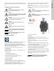
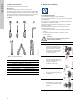
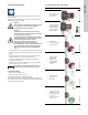
3.4 Frost protection Caution 1 Min./Max. +14 °F – 230 °F (-10 °C – +110 °C) 2 175 psi (12 bar) Note If the pump is not used during periods of frost, necessary steps must be taken to prevent frost bursts. Additives with a density and/or kinematic viscosity higher than those/that of water will reduce the hydraulic performance. 3.5 Insulating shells Insulating shells are available for single-head pumps only. 3 4 Note +32 to +104 °F (0 to +40 °C) <43 dB(A) Fig.
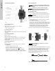
English (US) 3.7 Nameplate The pump nameplate provides the following information: TYPE 2 BOITIER DE TYPE 2 THERMALLY PROTECTED Nonsubmersible Pump PSI Contains FCC ID: OG3-RADIOM01-2G4 Fig. 5 Pos. RISQUE DE CHOC ELECTRIQUE. HORS DES EQUIPEMENT AVANT ENLEVEMENT DE LA COUVERTURE ET D’ENTRENTIEN. POUR LE RECCORDEMENT D’ALIMENTATION, EMPLOYEZ DES FILS QUI RESISTENT AU MOINS A 90 °C UTILISEZ UNIQUEMENT DES CONDUCTEURS DE CUIVRE.
The wireless radio in this product is class B. Intended use This product incorporates a radio for remote control. The product can communicate with the Grundfos Go Remote and with other MAGNA3 pumps of the same type via the built-in radio. Only Grundfos-approved external antennae may be connected to this product, and only by a Grundfos-approved installer. 1.2 x 8.0 4.1 Installing the pump The MAGNA3 is designed for indoor installation. 3.
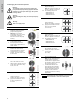
4.3 Control box positions Always install the pump with horizontal motor shaft. To ensure adequate cooling, the control box must be in horizontal position with the Grundfos logo in vertical position. See fig. 8. • Pump installed correctly in a vertical pipe. See fig. 7, pos. A. • Pump installed correctly in a horizontal pipe. See fig. 7, pos. B. • Do not install the pump with vertical motor shaft. See fig. 7, pos. C and D.
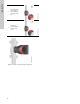
7 Fit the insulating shells. Note: For air conditioning and cooling systems a silicone sealant must be applied inside the insulation shell to eliminate all air gaps and prevent condensation between the pump housing and insulation shell. Alternatively, the pump may be insulated manually in accordance with standard insulation practices for cooling applications. Risk of escaping vapor. 8 2 Carefully rotate the pump head to the desired position.
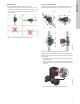
Step Action 1 Remove the front cover from the control box. 2 Locate the power supply plug and conduit adapter in the box supplied with the pump. 3 Connect the conduit adapter to the control box. 4 Pull the power supply cable through the conduit adapter and thread on conduit. 5 Strip the cable conductors as illustrated. 6 Connect the cable conductors to the power supply plug.
TM05 2881 0612 TM05 2882 0612 8 Tighten the conduit adapter. Refit the front cover. TM05 5549 3812 English (US) 7 Insert the power supply plug into the male plug in the pump control box. Fig.
English (US) 5.3 Connection diagram External switch ELCB TM03 2397 0312 Fuse (min. 10 A, time lag) Fig. 11 Example of typical connection, 1 x 230 V ± 10 %, 50/60 Hz Note All cables used must be connected in accordance with local regulations. 5.4 Connection to external controllers 3 Max. 250 V AC 2 A AC1 24V IN Vcc Signal 0-10 V DC Vcc Signal 4-20 mA Min. 5 V DC 20 mA I 2 M A M I S/S NC NO C 1 TM05 2901 1912 - TM05 3343 1212 Max. 24 V DC 22 mA Fig.
5.5.2 Digital inputs See fig. 12, pos. 1. See fig. 12, pos. 2. The pump incorporates two signal relays with a potential-free changeover contact for external fault indication. The digital input can be used for external control of start/stop or forced max. or min. curve. The function of the signal relay can be set to "Alarm", "Ready" or "Operation" on the pump control panel or with the Grundfos GO Remote.
The pump can be forced to operate on the max. or min. curve via the digital input. I H Vcc Normal duty signal sensor Q M A TM05 2948 0612 M A IN 24V Max. curve Fig. 16 Analog input for external sensor, 4-20 mA H Max. curve Q Min. curve M I 24V H Vcc Normal duty IN Signal Q M I H Min. curve Q TM05 2947 1212 Select the function of the digital input on the pump control panel or with the Grundfos GO Remote. 5.5.3 Analog input See fig. 12, pos. 3.
English (US) 5.6 Priority of settings The external forced-control signals will influence the settings available on the pump control panel or with the Grundfos GO Remote. However, the pump can always be set to max. curve duty or to stop on the pump control panel or with the Grundfos GO Remote. If two or more functions are enabled at the same time, the pump will operate according to the setting with the highest priority. The priority of the settings is as shown in the table below.
English (US) 6. First start-up Do not start the pump until the system has been filled with liquid and vented. Furthermore, the required minimum inlet pressure must be available at the pump inlet. See section 19. Technical data. The system cannot be vented through the pump. The pump is self-venting. 1 Switch on the power supply to the pump. Note: When switched on, the pump will start in AUTOADAPT after approx. 5 seconds. 2 Pump display at first start-up.
English (US) 7. Settings 7.1 Overview of settings All settings can be made on the pump control panel or with the Grundfos GO Remote. Menu Submenu Further information Setpoint See section 13.1 Setpoint. Operating mode See section 13.2 Operating mode. • Normal • Stop • Min. • Max. See section 13.3 Control mode. Control mode • AUTOADAPT See section 13.3.1 AUTOADAPT. • FLOWADAPT See section 13.3.2 FLOWADAPT. • Prop. press. See section 13.3.3 Proportional pressure. • Const. press. See section 13.
Status Settings Assist Operating status Setpoint Assisted pump setup Operating mode, from Operating mode Control mode Control mode Pump performance Setting of pump Setting of date and time Date format, date and time FLOWLIMIT Max.
Warning This menu enables assisted pump setup, provides a short description of the control modes and offers fault advice. See section 14. "Assist" menu. 11. "Home" menu TM05 7929 1613 At high liquid temperatures, the pump housing may be so hot that only the control panel should be touched to avoid burns. Navigation Home Press to go to the "Home" menu. "Home" menu (factory setting) TM05 7642 1313 Fig. 19 Control panel Button Function Goes to the "Home" menu.
3.1.0.0.0.0 Settings Navigation Navigation Home > Settings > Operating mode Home > Settings and go to the "Settings" menu with Operating mode . "Settings" menu • Normal (control mode) This menu offers the following setting options: • Stop • Setpoint • Min. (min. curve) • Operating mode • Max. (max. curve). • Control mode Setting: • FLOWLIMIT 1. Select operating mode with • Automatic Night Setback 2. Press [OK] to save.
3.1.3.0.0.0 Control mode Navigation Control mode Original duty point. Lower registered head on the max. curve. A 3: New duty point after AUTOADAPT control. Hset1: Original setpoint setting. Hset2: New setpoint after AUTOADAPT control. Hfac.: MAGNA3 MAGNA3 MAGNA3 MAGNA3 MAGNA3 MAGNA3 Hauto_min: A fixed value of 4.9 ft (1.5 m). xx-60: 11.4 ft (3.5 m) xx-80: 14.7 ft (4.5 m) xx-100: 18 ft (5.5 m) xx-120: 21.3 ft (6.5 m) xx-150: 26.2 ft (8.0 m) xx-180: 31.1 ft (9.5 m).
13.3.6 Differential temperature The pump maintains a constant pressure, irrespective of water demand. See fig. 24. This control mode ensures a constant differential temperature drop across a heating system. The pump should be installed in the flow pipe so the built-in sensor measures the fluid temperature going out to the load. An external temperature sensor must be installed in the system to measure the fluid temperature returning from the heating load.
The pump can be set to operate according to a constant curve, like an uncontrolled pump. See fig. 29. Kp System/application Heating system1) Ti Cooling system2) The desired speed can be set in % of maximum speed in the range from 25 to 100 %. H 0.5 - 0.5 10 + 5L2 t 0.5 Δt 10 + 5L2 Q L2 [m] Fig. 29 Constant curve L2 [m] t 0.5 - 0.5 30 + 5L2 Fig. 28 Table, suggested controller settings Note 1.
3.1.5.0.0.0 FLOWLIMIT Navigation Navigation Home > Settings > FLOWLIMIT Home > Settings > Automatic Night Setback FLOWLIMIT Automatic Night Setback • Enable FLOWLIMIT function • Set FLOWLIMIT. To enable the function, select "Active" with [OK]. Setting: 1. To enable the function, select "Active" with [OK]. or and press and and adjust with or .
• Not active The signal relay is deactivated. • Ready The signal relay is active when the pump is running or has been set to stop, but is ready to run. When this function is enabled in proportional- or constant-pressure control mode, the setpoint for head will be reduced according to the liquid temperature. Temperature influence can be set to function at liquid temperatures below +176 °F or +122 °F (80 °C or 50 °C). These temperature limits are called Tmax..
Set date and time 13.8.1 Pump number • Select date format • Set date • Select time format • Set time. English (US) 13.8 Bus communication 3.1.18.1.0.0 Pump number Set the real-time clock in this menu. Select date format • YYYY-MM-DD • DD-MM-YYYY • MM-DD-YYYY. Setting: 1. Select "Set date". 2. Press [OK] to start the setting. Navigation 3. Select digit with Home > Settings > Bus communication > Pump number 4. Press [OK] to save.
Navigation Home > Settings > General settings > Define Home display 3.1.19.4.0.0 Enable/disable settings Define Home display Navigation Enable/disable settings In this display, the possibility of making settings can be disabled for protective reasons. Select "Disable" with or and press [OK]. The pump will now be locked for settings. Only the "Home" display will be available. To unlock the pump and allow settings, press simultaneously for at least 5 seconds.
13.9.8 Return to factory settings Navigation Home > Settings > General settings > Return to factory settings Assist 3.1.19.10.1.0 Return to factory settings English (US) 14. "Assist" menu Navigation Home > Assist Return to factory settings Press It is possible to recall the factory settings and overwrite the current settings. All user settings in the "Settings" and "Assist" menus will be set back to the factory settings.
English (US) 14.8 Multi-pump function 14.8.2 Back-up operation The multi-pump function enables the control of single-head pumps connected in parallel and twin-head pumps without the use of external controllers. The pumps in a multi-pump system communicate with each other via the wireless GENIair connection. One pump is operating continuously. The back-up pump is operated at intervals to prevent seizing up. If the duty pump stops due to a fault, the back-up pump will start automatically.
System application Select this control mode Recommended for most heating systems, especially in systems with relatively large pressure losses in the distribution pipes. See description under proportional pressure. In replacement situations where the proportional-pressure duty point is unknown. AUTOADAPT H The duty point has to be within the AUTOADAPT operating range. During operation, the pump automatically makes the necessary adjustment to the actual system characteristic.
English (US) System application Select this control mode In a heating system where a constant temperature drop across the system is desired, constant differential temperature can be used. Differential temperature H ΔT Q If an external controller is installed, the pump is able to change from one constant curve to another, depending on the value of the external signal. The pump can also be set to operate according to the max. or min. curve, like an uncontrolled pump: • The max.
Warning Before dismantling the pump, drain the system or close the isolating valve on either side of the pump. The pumped liquid may be scalding hot and under high pressure. 16.1 Grundfos Eye operating indications Grundfos Eye Indication Cause No lights on. Power off. Pump not running. Two opposite green indicator lights running in the Power on. direction of rotation of the pump. Pump running. Two opposite green indicator lights permanently Power on. on. Pump not running.
English (US) 16.3 Fault finding A fault indication can be reset in one of the following ways: • When the fault cause has been eliminated, the pump will revert to normal duty. • If the fault disappears by itself, the fault indication will automatically be reset. • The fault cause will be stored in the pump alarm log. Warning and alarm codes Fault Pump communication fault (10) Alarm Communication fault between different parts of the electronics.
English (US) 17. Sensor 5 Nm TM05 3036 0812 Nose downwards Fig. 34 Correct position of sensor During maintenance and replacement of the sensor, it is important that the sealing cap is fitted correctly on the sensor housing. Tighten the screw holding the clamp to 3.7 ft-lbs (5 Nm). Warning Before replacing the sensor, make sure that the pump is stopped and that the system is not pressurized. 17.1 Sensor specifications 17.1.1 Pressure Maximum differential pressure during operation 29 psi / 2 bar / 0.
18.2 Communication The pump can communicate via the wireless GENIair connection or a CIM module. This enables the pump to communicate with other pumps and with different types of network solutions. 18.1 Grundfos GO Remote The Grundfos CIM modules (CIM = Communication Interface Module) enable the pump to connect to standard fieldbus networks. The MAGNA3 is designed for wireless communication with the Grundfos GO Remote app.
English (US) 18.3 Fitting the CIM module Warning Before fitting the module, switch off the power supply. Make sure that the power supply cannot be accidentally switched on. Step Action Remove the front cover from the control box. 2 Fit the CIM module as illustrated and click it on. 3 Fit and tighten the screw holding the CIM module and secure the earth connection. 4 For connection to fieldbus networks, see separate installation and operating instructions for the desired CIM module.
English (US) 19. Technical data Input/output communication Supply voltage See Pump Nameplate for Rated Supply Voltage: 1 x 115 V ± 10 %, 50/60 Hz, PE. Two digital inputs External potential-free contact. Contact load: 5 V, 10 mA. Screened cable. Loop resistance: Maximum 130 Ω. Analog input 4-20 mA (load: 150 Ω). 0-10 VDC (load: 78 kΩ). Two relay outputs Internal potential-free changeover contact. Maximum load: 250 V, 2 A, AC1. Minimum load: 5 VDC, 20 mA. Screened cable, depending on signal level.
GRUNDFOS Pumps Corporation 17100 West 118th Terrace Olathe, Kansas 66061 Phone: +1-913-227-3400 Telefax: +1-913-227-3500 Canada México GRUNDFOS Canada Inc. 2941 Brighton Road Oakville, Ontario L6H 6C9 Phone: +1-905 829 9533 Telefax: +1-905 829 9512 Bombas GRUNDFOS de México S.A. de C.V. Boulevard TLC No. 15 Parque Industrial Stiva Aeropuerto Apodaca, N.L.C.P.
98459408 0513 ECM: 1112321 www.grundfos.com www.grundfos.us The name Grundfos, the Grundfos logo, and be think innovate are registered trademarks owned by Grundfos Holding A/S or Grundfos A/S, Denmark. All rights reserved worldwide.