
Install Instructions
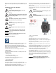
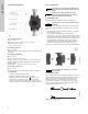
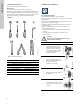
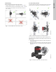
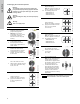
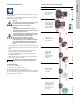
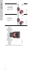
Table Of Contents
- English (US)
- 1. Limited warranty
- 2. Symbols used in this document
- 3. General information
- 4. Mechanical installation
- 5. Electrical installation
- 6. First start-up
- 7. Settings
- 8. Menu overview
- 9. Control panel
- 10. Menu structure
- 11. "Home" menu
- 12. "Status" menu
- 13. "Settings" menu
- 14. "Assist" menu
- 15. Selection of control mode
- 16. Fault finding
- 17. Sensor
- 18. Accessories
- 19. Technical data
- 20. Disposal

English (US)
8
4.4 Changing the control box position
Warning
The warning symbol on the clamp holding the
pump head and pump housing together indicates
that there is a risk of personal injury. See specific
warnings below.
Warning
When loosening the clamp, do not drop the pump
head.
Warning
Risk of escaping vapor.
Step Action Illustration
1
Loosen the screw in the clamp
holding the pump head and
pump housing together.
Warning: If the screw is
loosened too much, the pump
head will be completely
disconnected from the pump
housing.
TM05 2867 0612
2
Carefully rotate the pump head
to the desired position.
If the pump head is stuck,
loosen it with a light blow of a
rubber mallet.
TM05 2868 0612
3
Position the control box in
horizontal position so that the
Grundfos logo is in vertical
position. The motor shaft must
be horizontal.
TM05 2869 0612
4
Due to the drain hole in the
stator housing, position the gap
of the clamp as shown in step
4a, 4b, 4c or 4d.
TM05 2870 0612
4a
Single-head pump.
Position the clamp so that the
gap points towards the arrow.
It can be in position 3 or
9 o’clock.
TM05 2918 0612 - TM05 2871 0612
4b
Single-head pump.
Note: The gap of the clamp can
also be in position 6 o’clock for
the following pump sizes:
• MAGNA3 65-XX
• MAGNA3 80-XX
• MAGNA3 100-XX.
TM05 2899 1912
4c
Twin-head pump.
Position the clamps so that the
gaps point towards the arrows.
They can be in position
3 or 9 o’clock.
TM05 2917 0612 - TM05 2873 0612
4d
Twin-head pump.
Note: The gap of the clamp can
also be in position 6 o’clock for
the following pump sizes:
• MAGNA3 65-XX
• MAGNA3 80-XX
• MAGNA3 100-XX.
TM05 2897 1912
6
Fit and tighten the screw
holding the clamp to minimum
6 ± 0.7 ft-lbs
(8 ± 1 Nm).
TM05 2872 0612
7
Fit the insulating shells.
Note: For air conditioning and
cooling systems a silicone
sealant must be applied inside
the insulation shell to eliminate
all air gaps and prevent
condensation between the
pump housing and insulation
shell. Alternatively, the pump
may be insulated manually in
accordance with standard
insulation practices for cooling
applications.
TM05 2874 0412
Caution
If insulating the pump manually, do not insulate
the control box or cover the control panel.