
Install Instructions
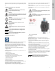
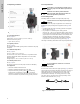
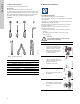
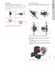
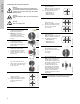
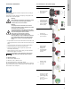
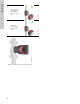
Table Of Contents
- English (US)
- 1. Limited warranty
- 2. Symbols used in this document
- 3. General information
- 4. Mechanical installation
- 5. Electrical installation
- 6. First start-up
- 7. Settings
- 8. Menu overview
- 9. Control panel
- 10. Menu structure
- 11. "Home" menu
- 12. "Status" menu
- 13. "Settings" menu
- 14. "Assist" menu
- 15. Selection of control mode
- 16. Fault finding
- 17. Sensor
- 18. Accessories
- 19. Technical data
- 20. Disposal

9
English (US)
5. Electrical installation
Carry out the electrical connection and protection according to
local regulations.
Check that the supply voltage and frequency correspond to the
values stated on the nameplate.
• If rigid conduit is to be used, the hub must be connected to the
conduit system before it is connected to the terminal box of the
pump.
• The pump must be connected to an external mains switch.
• The pump requires no external motor protection.
• The motor incorporates thermal protection against slow
overloading and blocking.
• When switched on via the power supply, the pump will start
pumping after approx. 5 seconds.
5.1 Supply voltage
1 x 115 V ± 10 %, 50/60 Hz, PE.
1 x 208-230 V ± 10 %, 50/60 Hz, PE.
See Pump Nameplate for rated supply voltage
The voltage tolerances are intended for mains voltage variations.
They should not be used for running pumps at other voltages than
those stated on the nameplate.
5.2 Connection to the power supply
Warning
Never make any connections in the pump control
box unless the electricity supply has been
switched off for at least 5 minutes.
Warning
The pump must be connected to an external
mains switch with a contact separation of at least
1/8 inch (3 mm) in each pole.
The ground terminal of the pump must be earth
ground. Grounding or neutralization can be used
for protection against indirect contact.
If the pump is connected to an electric
installation where a Ground Fault Circuit
Interrupt (GFCI) is used as additional protection,
this circuit breaker must trip out when ground
fault currents with DC content (pulsating DC)
occur.
Note
Note
The number of starts and stops via the power
supply must not exceed four times per hour.
Step Action Illustration
1
Remove the front
cover from the
control box.
TM05 2875 0612
2
Locate the power
supply plug and
conduit adapter in
the box supplied
with the pump.
TM05 2876 0612
3
Connect the
conduit adapter to
the control box.
TM05 2877 0612
4
Pull the power
supply cable
through the
conduit adapter
and thread on
conduit.
TM05 2878 0612
5
Strip the cable
conductors as
illustrated.
TM05 5534 3812
6
Connect the cable
conductors to the
power supply plug.
L - L or L1
Ground - Ground
N - N or L2
TM05 2880 0612