
Install Instructions
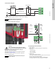
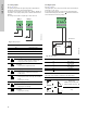
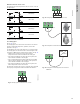
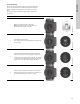
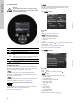
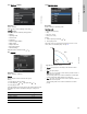
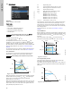
Table Of Contents
- English (US)
- 1. Limited warranty
- 2. Symbols used in this document
- 3. General information
- 4. Mechanical installation
- 5. Electrical installation
- 6. First start-up
- 7. Settings
- 8. Menu overview
- 9. Control panel
- 10. Menu structure
- 11. "Home" menu
- 12. "Status" menu
- 13. "Settings" menu
- 14. "Assist" menu
- 15. Selection of control mode
- 16. Fault finding
- 17. Sensor
- 18. Accessories
- 19. Technical data
- 20. Disposal

English (US)
12
5.5.1 Relay outputs
See fig. 12, pos. 1.
The pump incorporates two signal relays with a potential-free
changeover contact for external fault indication.
The function of the signal relay can be set to "Alarm", "Ready" or
"Operation" on the pump control panel or with the Grundfos GO
Remote.
The relays can be used for outputs up to 250 V and 2 A.
Fig. 13 Relay output
The functions of the signal relays appear from the table below:
5.5.2 Digital inputs
See fig. 12, pos. 2.
The digital input can be used for external control of start/stop or
forced max. or min. curve.
If no external on/off switch is connected, the jumper between
terminals Start/Stop (S/S) and frame ( ) should be maintain ed.
This connection is the factory setting.
Fig. 14 Digital input
External start/stop
The pump can be started or stopped via the digital input.
TM05 3338 1212
Contact symbol Function
NC Normally closed
NO Normally open
C Common
Signal relay Alarm signal
Not activated:
• The power supply has been switched off.
• The pump has not registered a fault.
Activated:
• The pump has registered a fault.
Signal relay Ready signal
Not activated:
• The pump has registered a fault and is
unable to run.
Activated:
• The pump has been set to stop, but is ready
to run.
• The pump is running.
Signal relay Operating signal
Not activated:
• The pump is not running.
Activated:
• The pump is running.
NC NO C NC NO C
Alarm
Operation
Relay 1 Relay 2
132
NC NO C
132
NC NO C
12 3
NC NO C
132
NC NO C
132
NC NO C
12 3
NC NO C
132
NC NO C
132
NC NO C
12 3
NC NO C
TM05 3339 1212
Contact symbol Function
M
A
Max. curve
100 % speed
M
I
Min. curve
25 % speed
S/S Start/Stop
Frame connection
Start/stop
Normal duty
Note: Factory setting with
jumper between S/S and .
Stop
S/S
M
I
M
A
On/off timer
Start/stop
S/S
Q
H
S/S
Q
H