
User Guide


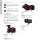
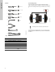
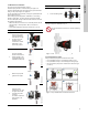
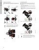
Table Of Contents
- English (US)
- 1. Limited warranty
- 2. General information
- 3. Receiving the product
- 4. Installing the product
- 5. Starting up the product
- 6. Handling and storing the product
- 7. Product introduction
- 8. Control functions
- 9. Setting the product
- 10. Servicing the product
- 11. Fault finding the product
- 12. Technical data
- 13. Accessories
- 14. Disposing of the product
- Français (CA)
- 1. Garantie limitée
- 2. Informations générales
- 3. Réception du produit
- 4. Installation du produit
- 4.1 Lieu d'installation
- 4.2 Outils
- 4.3 Coquilles d'isolation
- 4.4 Installation mécanique
- 4.5 Positionnement du circulateur
- 4.6 Positions du boîtier de commande
- 4.7 Position de la tête du circulateur
- 4.8 Modification de la position du boîtier de commande
- 4.9 Installation électrique
- 4.10 Branchement du câble de l'alimentation électrique
- 5. Démarrage du produit
- 6. Manutention et stockage du produit
- 7. Introduction au produit
- 8. Fonctions de régulation
- 8.1 Aperçu rapide des modes de régulation
- 8.2 Modes de fonctionnement
- 8.3 Modes de régulation
- 8.4 Fonctionnalités supplémentaires pour les modes de régulation
- 8.5 Modes circulateurs multiples
- 8.6 Valeurs de réglage pour les modes de régulation
- 8.7 Précision de l'estimation du débit
- 8.8 Tableau de la précision du débit
- 8.9 Branchements externes
- 8.10 Priorité des réglages
- 8.11 Communication entrée et sortie
- 9. Réglage du produit
- 10. Maintenance du produit
- 11. Détection des défauts de fonctionnement du produit
- 12. Caractéristiques techniques
- 13. Accessoires
- 14. Mise au rebut du produit
- Español (MX)
- 1. Garantía limitada
- 2. Información general
- 3. Recepción del producto
- 4. Instalación del producto
- 5. Puesta en marcha del producto
- 6. Manejo y almacenamiento del producto
- 7. Introducción de producto
- 8. Funciones de control
- 8.1 Breve resumen de los modos de control
- 8.2 Modos de operación
- 8.3 Modos de control
- 8.4 Otras funciones de los modos de control
- 8.5 Modos multibomba
- 8.6 Ajustes de los modos de control
- 8.7 Precisión de la estimación del caudal
- 8.8 Tabla de precisión del caudal
- 8.9 Conexiones externas
- 8.10 Prioridad de los ajustes
- 8.11 Comunicación de entrada y salida
- 9. Ajuste del producto
- 10. Mantenimiento y servicio del producto
- 11. Búsqueda de fallas del producto
- 12. Datos técnicos
- 13. Accesorios
- 14. Eliminación del producto
- Appendix

9
English (US)
4.4 Mechanical installation
The pump range includes flanged versions.
Install the pump so that it is not stressed by the pipes. For
maximum permissible forces and moments for pipe connections
acting on the pump flanges, see Appendix.
You can suspend the pump directly in the pipes, provided that the
pipes support the pump.
Twin-head pumps are prepared for installation on a mounting
bracket or base plate. The pump housing has an M12 thread.
To ensure adequate cooling of the motor and electronics, observe
the following requirements:
• Make sure that the control box is in horizontal position with the
Grundfos logo in vertical position. See 4.6 Control box
positions.
• The ambient temperature must not exceed 104 °F (40 °C).
As an alternative to insulating shells, you can insulate the pump
housing and pipes as illustrated in fig. 5.
Fig. 5 Insulation of the pump housing and pipe
4.5 Positioning the pump
Always install the pump with a horizontal motor shaft.
• Pump installed correctly in a vertical pipe. See fig. 6 (A).
• Pump installed correctly in a horizontal pipe. See fig. 6 (B).
• Do not install the pump with a vertical motor shaft. See fig. 6
(C and D).
Fig. 6 Pump installed with a horizontal motor shaft
Step Action Illustration
1
Arrows on the pump
housing indicate the
flow direction through
the pump. The flow
direction can be
horizontal or vertical,
depending on the
control box position.
TM05 8456 3216
2
Close the isolating
valves and make sure
that the system is not
pressurized during the
installation of the pump.
TM05 2863 3216
3
Mount the pump with
gaskets in the pipes.
TM05 2864 3216
4
Flanged version:
Fit bolts and nuts. Use
the right size of bolts
according to system
pressure.
For further information
about torques, see
Appendix.
TM05 8455 3216
5 Fit the insulating shells.
TM05 2874 3216
Do not insulate the control box or cover the operating
panel.
TM05 2889 3216TM05 2866 3216
Step Action Illustration
BA
DC