
User Guide

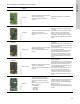
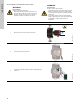
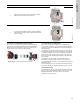
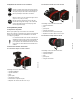
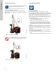
Table Of Contents
- English (US)
- 1. Limited warranty
- 2. General information
- 3. Receiving the product
- 4. Installing the product
- 5. Starting up the product
- 6. Handling and storing the product
- 7. Product introduction
- 8. Control functions
- 9. Setting the product
- 10. Servicing the product
- 11. Fault finding the product
- 12. Technical data
- 13. Accessories
- 14. Disposing of the product
- Français (CA)
- 1. Garantie limitée
- 2. Informations générales
- 3. Réception du produit
- 4. Installation du produit
- 4.1 Lieu d'installation
- 4.2 Outils
- 4.3 Coquilles d'isolation
- 4.4 Installation mécanique
- 4.5 Positionnement du circulateur
- 4.6 Positions du boîtier de commande
- 4.7 Position de la tête du circulateur
- 4.8 Modification de la position du boîtier de commande
- 4.9 Installation électrique
- 4.10 Branchement du câble de l'alimentation électrique
- 5. Démarrage du produit
- 6. Manutention et stockage du produit
- 7. Introduction au produit
- 8. Fonctions de régulation
- 8.1 Aperçu rapide des modes de régulation
- 8.2 Modes de fonctionnement
- 8.3 Modes de régulation
- 8.4 Fonctionnalités supplémentaires pour les modes de régulation
- 8.5 Modes circulateurs multiples
- 8.6 Valeurs de réglage pour les modes de régulation
- 8.7 Précision de l'estimation du débit
- 8.8 Tableau de la précision du débit
- 8.9 Branchements externes
- 8.10 Priorité des réglages
- 8.11 Communication entrée et sortie
- 9. Réglage du produit
- 10. Maintenance du produit
- 11. Détection des défauts de fonctionnement du produit
- 12. Caractéristiques techniques
- 13. Accessoires
- 14. Mise au rebut du produit
- Español (MX)
- 1. Garantía limitada
- 2. Información general
- 3. Recepción del producto
- 4. Instalación del producto
- 5. Puesta en marcha del producto
- 6. Manejo y almacenamiento del producto
- 7. Introducción de producto
- 8. Funciones de control
- 8.1 Breve resumen de los modos de control
- 8.2 Modos de operación
- 8.3 Modos de control
- 8.4 Otras funciones de los modos de control
- 8.5 Modos multibomba
- 8.6 Ajustes de los modos de control
- 8.7 Precisión de la estimación del caudal
- 8.8 Tabla de precisión del caudal
- 8.9 Conexiones externas
- 8.10 Prioridad de los ajustes
- 8.11 Comunicación de entrada y salida
- 9. Ajuste del producto
- 10. Mantenimiento y servicio del producto
- 11. Búsqueda de fallas del producto
- 12. Datos técnicos
- 13. Accesorios
- 14. Eliminación del producto
- Appendix

65
English (US)
13.2.3 Reuse of communication interface modules
You can reuse a communication interface module in a CIU unit
used together with Grundfos MAGNA Series 2000 in MAGNA3.
Before you use the CIM module in the pump, reconfigure the
module. Contact your nearest Grundfos company.
Fig. 66 Reuse of communication interface module
13.2.4 Auto detection of CIM modules
If a pump in a system with multiple pumps is replaced with a
newer version (model D), the new pump automatically detects if
the existing pump(s) and/or BMS system are older and adjusts
itself accordingly.
Auto detection in twin-head pumps happens if one of the pumps
is replaced and paired with a newer model than the existing one,
i.e. MAGNA3 model D. The new pump automatically detects the
model version of the existing pump. If the old pump is an older
model, the new pump will adjust itself making it compatible with
the old system.
Auto detection can be manually overruled if the system is
controlled by a SCADA system. However, when integrating a
newer model with an older setup, we recommend that you choose
compatibility mode.
For more information on how to manage auto detection directly
on the pump, see section "Multipump profile selection", page 50.
13.3 Counterflanges
Counterflange kits consist of two flanges, two gaskets and bolts
and nuts, making it possible to install the pump in any pipe. See
MAGNA3 data booklet, Accessories section, for the right
dimension and product number.
4
Tighten the screw holding the communication interface
module and secure the ground connection.
TM05 2912 3416
5
For connection to fieldbus networks, see the installation
and operating instructions for the desired communication
interface module.
TM05 2913 3416
Step Action Illustration
TM05 2911 1312