
User Guide

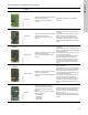
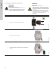
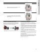
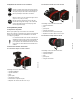
Table Of Contents
- English (US)
- 1. Limited warranty
- 2. General information
- 3. Receiving the product
- 4. Installing the product
- 5. Starting up the product
- 6. Handling and storing the product
- 7. Product introduction
- 8. Control functions
- 9. Setting the product
- 10. Servicing the product
- 11. Fault finding the product
- 12. Technical data
- 13. Accessories
- 14. Disposing of the product
- Français (CA)
- 1. Garantie limitée
- 2. Informations générales
- 3. Réception du produit
- 4. Installation du produit
- 4.1 Lieu d'installation
- 4.2 Outils
- 4.3 Coquilles d'isolation
- 4.4 Installation mécanique
- 4.5 Positionnement du circulateur
- 4.6 Positions du boîtier de commande
- 4.7 Position de la tête du circulateur
- 4.8 Modification de la position du boîtier de commande
- 4.9 Installation électrique
- 4.10 Branchement du câble de l'alimentation électrique
- 5. Démarrage du produit
- 6. Manutention et stockage du produit
- 7. Introduction au produit
- 8. Fonctions de régulation
- 8.1 Aperçu rapide des modes de régulation
- 8.2 Modes de fonctionnement
- 8.3 Modes de régulation
- 8.4 Fonctionnalités supplémentaires pour les modes de régulation
- 8.5 Modes circulateurs multiples
- 8.6 Valeurs de réglage pour les modes de régulation
- 8.7 Précision de l'estimation du débit
- 8.8 Tableau de la précision du débit
- 8.9 Branchements externes
- 8.10 Priorité des réglages
- 8.11 Communication entrée et sortie
- 9. Réglage du produit
- 10. Maintenance du produit
- 11. Détection des défauts de fonctionnement du produit
- 12. Caractéristiques techniques
- 13. Accessoires
- 14. Mise au rebut du produit
- Español (MX)
- 1. Garantía limitada
- 2. Información general
- 3. Recepción del producto
- 4. Instalación del producto
- 5. Puesta en marcha del producto
- 6. Manejo y almacenamiento del producto
- 7. Introducción de producto
- 8. Funciones de control
- 8.1 Breve resumen de los modos de control
- 8.2 Modos de operación
- 8.3 Modos de control
- 8.4 Otras funciones de los modos de control
- 8.5 Modos multibomba
- 8.6 Ajustes de los modos de control
- 8.7 Precisión de la estimación del caudal
- 8.8 Tabla de precisión del caudal
- 8.9 Conexiones externas
- 8.10 Prioridad de los ajustes
- 8.11 Comunicación de entrada y salida
- 9. Ajuste del producto
- 10. Mantenimiento y servicio del producto
- 11. Búsqueda de fallas del producto
- 12. Datos técnicos
- 13. Accesorios
- 14. Eliminación del producto
- Appendix

63
English (US)
13.2.1 Description of communication interface modules
Module
Fieldbus
protocol
Description Functions
CIM 050
TM06 7238 3416
GENIbus
CIM 050 is a Grundfos communication
interface module used for
communication with a GENIbus
network.
CIM 050 has terminals for the GENIbus
connection.
CIM 100
TM06 7279 3416
LonWorks
CIM 100 is a Grundfos communication
interface module used for
communication with a LonWorks
network.
CIM 100 has terminals for the LonWorks
connection.
Two LEDs are used to indicate the actual
status of the CIM 100 communication.
One LED is used for indication of correct
connection to the pump, and the other is
used to indicate LonWorks communication
status.
CIM 200
TM06 7281 3416
Modbus RTU
CIM 200 is a Grundfos communication
interface module used for
communication with a Modbus RTU
network.
CIM 200 has terminals for the Modbus
connection.
DIP switches are used to select parity and
stop bits, to select transmission speed and
to set line termination.
Two hexadecimal rotary switches are used
to set the Modbus address.
Two LEDs are used to indicate the actual
status of the CIM 200 communication.
One LED is used for indication of correct
connection to the pump, and the other is
used to indicate Modbus communication
status.
CIM 300
TM06 7281 3416
BACnet MS/TP
CIM 300 is a Grundfos communication
interface module used for
communication with a BACnet MS/TP
network.
CIM 300 has terminals for the BACnet
MS/TP connection.
DIP switches are used to set transmission
speed and line termination and to select the
custom Device Object Instance Number.
Two hexadecimal rotary switches are used
to set the BACnet address.
Two LEDs are used to indicate the actual
status of the CIM 300 communication.
One LED is used for indication of correct
connection to the pump, and the other is
used to indicate BACnet communication
status.
CIM 500
TM06 7283 3416
Ethernet
CIM 500 is a Grundfos communication
interface module used for data
transmission between an industrial
ethernet network and a Grundfos
product.
CIM 500 supports various industrial
ethernet protocols:
• PROFINET
• Modbus TCP
• BACnet/IP
• Ethernet/IP
CIM 500 supports various industrial ethernet
protocols. CIM 500 is configured via the
built-in web server, using a standard web
browser on a PC.
See the specific functional profile on the
DVD-ROM supplied with the Grundfos CIM
module.