
User Guide
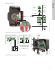
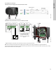
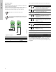
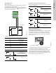
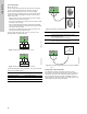
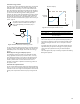
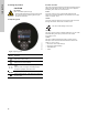
Table Of Contents
- English (US)
- 1. Limited warranty
- 2. General information
- 3. Receiving the product
- 4. Installing the product
- 5. Starting up the product
- 6. Handling and storing the product
- 7. Product introduction
- 8. Control functions
- 9. Setting the product
- 10. Servicing the product
- 11. Fault finding the product
- 12. Technical data
- 13. Accessories
- 14. Disposing of the product
- Français (CA)
- 1. Garantie limitée
- 2. Informations générales
- 3. Réception du produit
- 4. Installation du produit
- 4.1 Lieu d'installation
- 4.2 Outils
- 4.3 Coquilles d'isolation
- 4.4 Installation mécanique
- 4.5 Positionnement du circulateur
- 4.6 Positions du boîtier de commande
- 4.7 Position de la tête du circulateur
- 4.8 Modification de la position du boîtier de commande
- 4.9 Installation électrique
- 4.10 Branchement du câble de l'alimentation électrique
- 5. Démarrage du produit
- 6. Manutention et stockage du produit
- 7. Introduction au produit
- 8. Fonctions de régulation
- 8.1 Aperçu rapide des modes de régulation
- 8.2 Modes de fonctionnement
- 8.3 Modes de régulation
- 8.4 Fonctionnalités supplémentaires pour les modes de régulation
- 8.5 Modes circulateurs multiples
- 8.6 Valeurs de réglage pour les modes de régulation
- 8.7 Précision de l'estimation du débit
- 8.8 Tableau de la précision du débit
- 8.9 Branchements externes
- 8.10 Priorité des réglages
- 8.11 Communication entrée et sortie
- 9. Réglage du produit
- 10. Maintenance du produit
- 11. Détection des défauts de fonctionnement du produit
- 12. Caractéristiques techniques
- 13. Accessoires
- 14. Mise au rebut du produit
- Español (MX)
- 1. Garantía limitada
- 2. Información general
- 3. Recepción del producto
- 4. Instalación del producto
- 5. Puesta en marcha del producto
- 6. Manejo y almacenamiento del producto
- 7. Introducción de producto
- 8. Funciones de control
- 8.1 Breve resumen de los modos de control
- 8.2 Modos de operación
- 8.3 Modos de control
- 8.4 Otras funciones de los modos de control
- 8.5 Modos multibomba
- 8.6 Ajustes de los modos de control
- 8.7 Precisión de la estimación del caudal
- 8.8 Tabla de precisión del caudal
- 8.9 Conexiones externas
- 8.10 Prioridad de los ajustes
- 8.11 Comunicación de entrada y salida
- 9. Ajuste del producto
- 10. Mantenimiento y servicio del producto
- 11. Búsqueda de fallas del producto
- 12. Datos técnicos
- 13. Accesorios
- 14. Eliminación del producto
- Appendix

39
English (US)
8.11.5 Heat energy monitor
The heat energy monitor calculates the heat energy consumption
within the system. The built-in flow estimation needed for the
calculation has an inaccuracy of ± 10 % of the maximum flow.
Also, the temperature measurements needed for the calculation
have some inaccuracy depending on the sensor type. Therefore,
you cannot use the heat energy value for billing purposes.
However, the value is perfect for optimization purposes in order to
prevent excessive energy costs caused by system imbalances.
The flow and volume accuracy is calculated and shown in the
display, see sections "Estimated flow", page 44, and "Accuracy of
values", page 44.
Fig. 53 MAGNA3 with built-in heat energy monitor
You can measure both heating and cooling in the same system. If
a system is used for both heating and cooling, two counters are
automatically shown in the display. See section "Heat energy",
page 44.
Monitoring heat energy in multipump systems
In a multipump system, the master pump calculates the heat
energy regardless of which pump, master or slave, is running.
If the master loses power or has a fault on the external sensor,
the accumulation of heat energy will not be counted until the
master is powered back on or the external sensor error is
remedied. If the master is replaced, the heat energy values for
the system is reset.
8.11.6 External setpoint function
You can use the analog input to influence the setpoint externally.
Here, a 0-10 V or 4-20 mA signal controls the pump speed range
in a linear function. The range of control depends on the minimum
speed, power and pressure limits of the pump. See figs 54 and
55.
Fig. 54 External setpoint function, 0-10 V
Fig. 55 Control range and setpoint
The external setpoint function operates differently depending on
the model. For models A, B and C, the maximum speed is often
obtained at voltages lower than 10 V, as the span of control is
limited.
In models newer than A, B and C, the internal scaling has been
optimized making the dynamic area bigger, thus giving a better
control of the pump speed when using the external setpoint
function.
The same applies if the pump is receiving a setpoint from Building
Management Systems.
The heat energy monitor requires an additional
temperature sensor installed in the flow pipe or
return pipe depending on where the pump is
installed.
TM05 5367 3612
t
kWh
F
t
R
TM06 9149 2117
Control
0-2 V (0-20 %) Resulting setpoint is equal to minimum.
2-10 V (20-100 %)
Resulting setpoint is between minimum
and user setpoint.
V
1020
H
(user setpoint)
Analog input
Resulting
setpoint