
User Guide
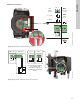
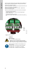
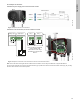
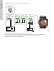
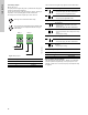
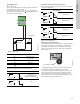
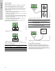
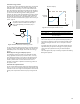
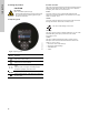
Table Of Contents
- English (US)
- 1. Limited warranty
- 2. General information
- 3. Receiving the product
- 4. Installing the product
- 5. Starting up the product
- 6. Handling and storing the product
- 7. Product introduction
- 8. Control functions
- 9. Setting the product
- 10. Servicing the product
- 11. Fault finding the product
- 12. Technical data
- 13. Accessories
- 14. Disposing of the product
- Français (CA)
- 1. Garantie limitée
- 2. Informations générales
- 3. Réception du produit
- 4. Installation du produit
- 4.1 Lieu d'installation
- 4.2 Outils
- 4.3 Coquilles d'isolation
- 4.4 Installation mécanique
- 4.5 Positionnement du circulateur
- 4.6 Positions du boîtier de commande
- 4.7 Position de la tête du circulateur
- 4.8 Modification de la position du boîtier de commande
- 4.9 Installation électrique
- 4.10 Branchement du câble de l'alimentation électrique
- 5. Démarrage du produit
- 6. Manutention et stockage du produit
- 7. Introduction au produit
- 8. Fonctions de régulation
- 8.1 Aperçu rapide des modes de régulation
- 8.2 Modes de fonctionnement
- 8.3 Modes de régulation
- 8.4 Fonctionnalités supplémentaires pour les modes de régulation
- 8.5 Modes circulateurs multiples
- 8.6 Valeurs de réglage pour les modes de régulation
- 8.7 Précision de l'estimation du débit
- 8.8 Tableau de la précision du débit
- 8.9 Branchements externes
- 8.10 Priorité des réglages
- 8.11 Communication entrée et sortie
- 9. Réglage du produit
- 10. Maintenance du produit
- 11. Détection des défauts de fonctionnement du produit
- 12. Caractéristiques techniques
- 13. Accessoires
- 14. Mise au rebut du produit
- Español (MX)
- 1. Garantía limitada
- 2. Información general
- 3. Recepción del producto
- 4. Instalación del producto
- 5. Puesta en marcha del producto
- 6. Manejo y almacenamiento del producto
- 7. Introducción de producto
- 8. Funciones de control
- 8.1 Breve resumen de los modos de control
- 8.2 Modos de operación
- 8.3 Modos de control
- 8.4 Otras funciones de los modos de control
- 8.5 Modos multibomba
- 8.6 Ajustes de los modos de control
- 8.7 Precisión de la estimación del caudal
- 8.8 Tabla de precisión del caudal
- 8.9 Conexiones externas
- 8.10 Prioridad de los ajustes
- 8.11 Comunicación de entrada y salida
- 9. Ajuste del producto
- 10. Mantenimiento y servicio del producto
- 11. Búsqueda de fallas del producto
- 12. Datos técnicos
- 13. Accesorios
- 14. Eliminación del producto
- Appendix

English (US)
38
8.11.4 Analog input
See fig. 40, pos. 3.
You can use the analog input for the connection of an external
sensor for measuring temperature or pressure. See fig. 51.
You can use sensor types with 0-10 V or 4-20 mA signal.
You can also use the analog input for an external signal for the
control from a building management system or similar control
system. See fig. 52.
• When the input is used for the heat energy monitor, install a
temperature sensor in the return pipe.
• If the pump is installed in the return pipe of the system, install
the sensor in the flow pipe.
• If the constant-temperature control mode has been enabled
and the pump is installed in the flow pipe of the system, install
the sensor in the return pipe.
• If the pump is installed in the return pipe of the system, you
can use the internal temperature sensor.
You can change the sensor type, 0-10 V or 4-20 mA, on the
operating panel or with Grundfos GO.
Fig. 49 Analog input for external sensor, 0-10 V
Fig. 50 Analog input for external sensor, 4-20 mA
In order to optimize the pump performance, you can use external
sensors in the following cases:
Fig. 51 Examples of external sensors
For further details, see section 13.4 External sensors.
Fig. 52 Examples of external signal for the control via BMS or
PLC
Analog input on twin-head pumps
For redundancy purposes, the analog input can be used
concurrently on the slave pump head. As long as the master is
powered up, the input on the slave will be ignored. However, in
the event of power loss on the master, the analog input of the
slave will take over. When the master pump head is back on, the
master takes over and controls the system.
TM05 3221 0612TM05 2948 0612
Function or control mode Sensor type
Heat energy monitor Temperature sensor
Constant temperature Temperature sensor
Proportional pressure Pressure sensor
signal
sensor
Vcc
24V
I
N
signal
sensor
Vcc
24V
I
N
signal
sensor
Vcc
I
24V
I
N
TM06 7237 3416
Pos. Sensor type
1
Combined temperature and pressure sensor,
Grundfos type RPI T2.
1/2" connection and 4-20 mA signal.
2
Pressure sensor, Grundfos type RPI.
1/2" connection and 4-20 mA signal.
TM05 2888 0612
24V IN
Vcc
Signal
1
2
24V
BMS
PLC