
User Guide
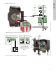
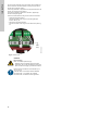
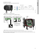
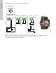
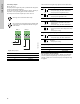
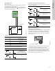
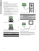
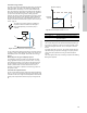
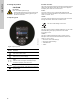
Table Of Contents
- English (US)
- 1. Limited warranty
- 2. General information
- 3. Receiving the product
- 4. Installing the product
- 5. Starting up the product
- 6. Handling and storing the product
- 7. Product introduction
- 8. Control functions
- 9. Setting the product
- 10. Servicing the product
- 11. Fault finding the product
- 12. Technical data
- 13. Accessories
- 14. Disposing of the product
- Français (CA)
- 1. Garantie limitée
- 2. Informations générales
- 3. Réception du produit
- 4. Installation du produit
- 4.1 Lieu d'installation
- 4.2 Outils
- 4.3 Coquilles d'isolation
- 4.4 Installation mécanique
- 4.5 Positionnement du circulateur
- 4.6 Positions du boîtier de commande
- 4.7 Position de la tête du circulateur
- 4.8 Modification de la position du boîtier de commande
- 4.9 Installation électrique
- 4.10 Branchement du câble de l'alimentation électrique
- 5. Démarrage du produit
- 6. Manutention et stockage du produit
- 7. Introduction au produit
- 8. Fonctions de régulation
- 8.1 Aperçu rapide des modes de régulation
- 8.2 Modes de fonctionnement
- 8.3 Modes de régulation
- 8.4 Fonctionnalités supplémentaires pour les modes de régulation
- 8.5 Modes circulateurs multiples
- 8.6 Valeurs de réglage pour les modes de régulation
- 8.7 Précision de l'estimation du débit
- 8.8 Tableau de la précision du débit
- 8.9 Branchements externes
- 8.10 Priorité des réglages
- 8.11 Communication entrée et sortie
- 9. Réglage du produit
- 10. Maintenance du produit
- 11. Détection des défauts de fonctionnement du produit
- 12. Caractéristiques techniques
- 13. Accessoires
- 14. Mise au rebut du produit
- Español (MX)
- 1. Garantía limitada
- 2. Información general
- 3. Recepción del producto
- 4. Instalación del producto
- 5. Puesta en marcha del producto
- 6. Manejo y almacenamiento del producto
- 7. Introducción de producto
- 8. Funciones de control
- 8.1 Breve resumen de los modos de control
- 8.2 Modos de operación
- 8.3 Modos de control
- 8.4 Otras funciones de los modos de control
- 8.5 Modos multibomba
- 8.6 Ajustes de los modos de control
- 8.7 Precisión de la estimación del caudal
- 8.8 Tabla de precisión del caudal
- 8.9 Conexiones externas
- 8.10 Prioridad de los ajustes
- 8.11 Comunicación de entrada y salida
- 9. Ajuste del producto
- 10. Mantenimiento y servicio del producto
- 11. Búsqueda de fallas del producto
- 12. Datos técnicos
- 13. Accesorios
- 14. Eliminación del producto
- Appendix

37
English (US)
8.11.3 Digital inputs
See fig. 40, pos. 2.
You can use the digital input for external control of start-stop or
forced maximum or minimum curve.
If no external on-off switch is connected, the jumper between
terminals start-stop (S/S) and frame ( ) must be maintained. This
connection is the factory setting.
Fig. 47 Digital input
External start-stop
You can start and stop the pump via the digital input.
Externally forced maximum or minimum curve
You can force the pump to operate on the maximum or minimum
curve via the digital input.
Select the function of the digital input on the pump operating
panel or with Grundfos GO.
Digital input on twin-head pumps
The Start/Stop input operates on system level, meaning that if the
master pump head receives a stop signal, the system stops.
As a main rule, the digital input is only effective on the master,
which is why it is important to know which pump is assigned as
master, see fig. 48.
Fig. 48 Identifying the master pump head on the nameplate
For redundancy purposes, the digital input can be used
concurrently on the slave pump head. However, as long as the
master is powered up, the input on the slave will be ignored. In
the event of power loss on the master, the digital input of the
slave will take over. When the master pump head is back on, the
master takes over and controls the system.
TM05 3339 1212
Contact symbol Function
M
A
Maximum curve
100 % speed
M
I
Minimum curve
S/S Start-stop
Frame connection
Start-stop
Normal duty
Factory setting with jumper
between start-stop and .
Stop
S/S
M
I
M
A
On-off timer
Start-stop
S/S
Q
H
S/S
Q
H
Maximum curve
Normal duty
Maximum curve
Minimum curve
Normal duty
Minimum curve
TM06 9088 4117
M
A
Q
H
M
A
Q
H
M
I
Q
H
M
I
Q
H
XXXXXXXXXXXXXXXXXXXXXXXX
P/N: XXXXXXXX
S/N: XXXXXXXX
PC: XXXX
Model: X
((,;;;3DUW;
0LQ
0D[
;;;
;;
XXXX
XXXX;;;
I
1
[A] P1 [W] 03D
Assembled In USA
I is defined as master.