
User Guide
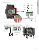
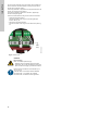
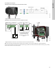
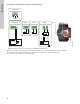
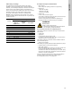
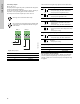
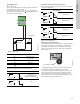
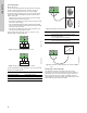
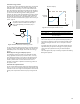
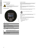
Table Of Contents
- English (US)
- 1. Limited warranty
- 2. General information
- 3. Receiving the product
- 4. Installing the product
- 5. Starting up the product
- 6. Handling and storing the product
- 7. Product introduction
- 8. Control functions
- 9. Setting the product
- 10. Servicing the product
- 11. Fault finding the product
- 12. Technical data
- 13. Accessories
- 14. Disposing of the product
- Français (CA)
- 1. Garantie limitée
- 2. Informations générales
- 3. Réception du produit
- 4. Installation du produit
- 4.1 Lieu d'installation
- 4.2 Outils
- 4.3 Coquilles d'isolation
- 4.4 Installation mécanique
- 4.5 Positionnement du circulateur
- 4.6 Positions du boîtier de commande
- 4.7 Position de la tête du circulateur
- 4.8 Modification de la position du boîtier de commande
- 4.9 Installation électrique
- 4.10 Branchement du câble de l'alimentation électrique
- 5. Démarrage du produit
- 6. Manutention et stockage du produit
- 7. Introduction au produit
- 8. Fonctions de régulation
- 8.1 Aperçu rapide des modes de régulation
- 8.2 Modes de fonctionnement
- 8.3 Modes de régulation
- 8.4 Fonctionnalités supplémentaires pour les modes de régulation
- 8.5 Modes circulateurs multiples
- 8.6 Valeurs de réglage pour les modes de régulation
- 8.7 Précision de l'estimation du débit
- 8.8 Tableau de la précision du débit
- 8.9 Branchements externes
- 8.10 Priorité des réglages
- 8.11 Communication entrée et sortie
- 9. Réglage du produit
- 10. Maintenance du produit
- 11. Détection des défauts de fonctionnement du produit
- 12. Caractéristiques techniques
- 13. Accessoires
- 14. Mise au rebut du produit
- Español (MX)
- 1. Garantía limitada
- 2. Información general
- 3. Recepción del producto
- 4. Instalación del producto
- 5. Puesta en marcha del producto
- 6. Manejo y almacenamiento del producto
- 7. Introducción de producto
- 8. Funciones de control
- 8.1 Breve resumen de los modos de control
- 8.2 Modos de operación
- 8.3 Modos de control
- 8.4 Otras funciones de los modos de control
- 8.5 Modos multibomba
- 8.6 Ajustes de los modos de control
- 8.7 Precisión de la estimación del caudal
- 8.8 Tabla de precisión del caudal
- 8.9 Conexiones externas
- 8.10 Prioridad de los ajustes
- 8.11 Comunicación de entrada y salida
- 9. Ajuste del producto
- 10. Mantenimiento y servicio del producto
- 11. Búsqueda de fallas del producto
- 12. Datos técnicos
- 13. Accesorios
- 14. Eliminación del producto
- Appendix

35
English (US)
8.10 Priority of settings
The external forced-control signals influence the settings
available on the pump operating panel or with Grundfos GO.
However, you can always set the pump to maximum-curve duty or
stop the pump on the operating panel or with Grundfos GO.
If two or more functions are enabled at the same time, the pump
operates according to the setting with the highest priority.
The priority of the settings is as shown in the table below.
Example: If the pump has been forced to stop via an external
signal, the operating panel or Grundfos GO can only set the pump
to maximum curve.
8.11 Input and output communication
• Relay outputs
Alarm, ready and operating indication via signal relay.
• Digital input
– Start and stop (S/S)
– Minimum curve (MI)
– Maximum curve (MA).
• Analog input
0-10 V or 4-20 mA control signal.
To be used for external control of the pump or as sensor input
for the control of the external setpoint.
The 24-V supply from pump to sensor is optional and is
normally used when an external supply is not available.
8.11.1 External connections in a multipump system
The following external connections need only to be fitted to the
master pump:
• analog input
• digital input
• communication interface module, CIM
If you want to monitor a slave pump, mount a communication
interface module on the slave pump too.
The following external connections need to be fitted on both the
master and slave pumps:
• Relays (from model B)
The following are system parameters shared between the pumps:
• Operating mode, control mode and setpoint
• Heat energy monitor:
Both pumps display the heat energy for the entire system and
not only for the individual pump. Please note that all
calculations are made in the master pump. If the master pump
loses power, the heat energy will cease to increment. See also
section 8.11.5 Heat energy monitor.
For more information about input and output communication in
multipump systems, see sections 8.11.2 Relay outputs,
8.11.3 Digital inputs and 8.11.4 Analog input.
Priority
Possible settings
Operating
panel or
Grundfos GO
External
signals
Bus signal
1 "Stop"
2"Max. curve"
3 "Stop"
4"Stop"
5 "Max. curve"
6 "Min. curve"
7"Start"
8 "Max. curve"
9"Min. curve"
10 "Min. curve"
11 "Start"
WARNING
Electric shock
Death or serious personal injury
- Separate input voltages from external equipment
from live parts by reinforced insulation.