
User Guide
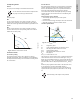
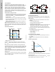
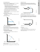
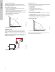
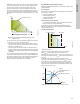
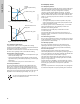
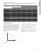
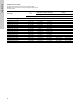
Table Of Contents
- English (US)
- 1. Limited warranty
- 2. General information
- 3. Receiving the product
- 4. Installing the product
- 5. Starting up the product
- 6. Handling and storing the product
- 7. Product introduction
- 8. Control functions
- 9. Setting the product
- 10. Servicing the product
- 11. Fault finding the product
- 12. Technical data
- 13. Accessories
- 14. Disposing of the product
- Français (CA)
- 1. Garantie limitée
- 2. Informations générales
- 3. Réception du produit
- 4. Installation du produit
- 4.1 Lieu d'installation
- 4.2 Outils
- 4.3 Coquilles d'isolation
- 4.4 Installation mécanique
- 4.5 Positionnement du circulateur
- 4.6 Positions du boîtier de commande
- 4.7 Position de la tête du circulateur
- 4.8 Modification de la position du boîtier de commande
- 4.9 Installation électrique
- 4.10 Branchement du câble de l'alimentation électrique
- 5. Démarrage du produit
- 6. Manutention et stockage du produit
- 7. Introduction au produit
- 8. Fonctions de régulation
- 8.1 Aperçu rapide des modes de régulation
- 8.2 Modes de fonctionnement
- 8.3 Modes de régulation
- 8.4 Fonctionnalités supplémentaires pour les modes de régulation
- 8.5 Modes circulateurs multiples
- 8.6 Valeurs de réglage pour les modes de régulation
- 8.7 Précision de l'estimation du débit
- 8.8 Tableau de la précision du débit
- 8.9 Branchements externes
- 8.10 Priorité des réglages
- 8.11 Communication entrée et sortie
- 9. Réglage du produit
- 10. Maintenance du produit
- 11. Détection des défauts de fonctionnement du produit
- 12. Caractéristiques techniques
- 13. Accessoires
- 14. Mise au rebut du produit
- Español (MX)
- 1. Garantía limitada
- 2. Información general
- 3. Recepción del producto
- 4. Instalación del producto
- 5. Puesta en marcha del producto
- 6. Manejo y almacenamiento del producto
- 7. Introducción de producto
- 8. Funciones de control
- 8.1 Breve resumen de los modos de control
- 8.2 Modos de operación
- 8.3 Modos de control
- 8.4 Otras funciones de los modos de control
- 8.5 Modos multibomba
- 8.6 Ajustes de los modos de control
- 8.7 Precisión de la estimación del caudal
- 8.8 Tabla de precisión del caudal
- 8.9 Conexiones externas
- 8.10 Prioridad de los ajustes
- 8.11 Comunicación de entrada y salida
- 9. Ajuste del producto
- 10. Mantenimiento y servicio del producto
- 11. Búsqueda de fallas del producto
- 12. Datos técnicos
- 13. Accesorios
- 14. Eliminación del producto
- Appendix

29
English (US)
8.6 Setting values for control modes
The setting values for FLOW
ADAPT
and FLOW
LIMIT
are indicated in % of maximum flow, but you must enter the value in m
3
/h in the
"Settings" menu. The maximum flow is a theoretical value corresponding to H = 0. The actual maximum flow depends on the system
characteristics.
The duty ranges for proportional-pressure and constant-pressure control appear in the MAGNA3 data booklet.
In constant-curve duty, you can control the pump from minimum to 100 %. The range of control depends on the minimum speed, power
and pressure limits of the pump.
8.7 Flow estimation accuracy
The internal sensor estimates the difference in pressure between
the inlet and outlet port of the pump. The measurement is not a
direct differential-pressure measurement, but by knowing the
hydraulic design of the pump, you can estimate the differential
pressure across the pump. The speed and power give a direct
estimation of the actual duty point at which the pump is running.
The calculated flow rate has an accuracy specified as +/- xx % of
Q
max
. The less flow through the pump, the less accurate the
reading will be. See also section 8.11.5 Heat energy monitor.
Example:
Fig. 39 Q
max
1. MAGNA3 65-60 has a Q
max
of 40 m
3
/h.
Typically 5 % accuracy means 2 m
3
/h inaccuracy of Q
max
± 2
m
3
/h.
2. This accuracy is valid for the entire QH area. If the pump
indicates 10 m
3
/h, the measurement is 10 ± 2 m
3
/h.
3. The flow rate can be from 8-12 m
3
/h.
The use of a mixture of water and ethylene-glycol will reduce the
accuracy.
If the flow is less than 10 % of Q
max
, the display shows a low flow.
See section 8.8 Flow accuracy table, section 8.9 External
connections, for flow accuracy calculations of the complete
MAGNA3 range.
AUTO
ADAPT
H
fac
Q
max
FLOW
ADAPT
/ FLOW
LIMIT
Q
fac
Q
min
25 % Q
max
90 %
[ft (m)] [gpm (m
3
/h)] [gpm (m
3
/h)] [gpm (m
3
/h)] [gpm (m
3
/h)]
Single-head pump type
MAGNA3 32-60 F (N) 11.5 (3.5) 48.5 (11.0) 26.0 (5.9) 12.4 (2.8) 43.6 (9.9)
MAGNA3 32-100 F (N) 18.1 (5.5) 57.3 (13.0) 29.5 (6.7) 14.6 (3.3) 51.6 (11.7)
MAGNA3 40-80 F (N) 14.8 (4.5) 94.7 (21.5) 57.2 (13) 23.8 (5.4) 85.4 (19.4)
MAGNA3 40-120 F (N) 21.3 (6.5) 112.2 (25.5) 70.4 (16) 28.2 (6.4) 101.2 (23)
MAGNA3 40-180 F (N) 31.2 (9.5) 125.4 (28.5) 66.0 (15) 31.2 (7.1) 113.1 (25.7)
MAGNA3 50-80 F (N) 14.8 (4.5) 129.8 (29.5) 74.8 (17) 32.6 (7.4) 117.0 (26.6)
MAGNA3 50-150 F (N) 26.2 (8.0) 165.0 (37.5) 88.0 (20) 41.4 (9.4) 148.7 (33.8)
MAGNA3 65-120 F (N) 21.3 (6.5) 209.0 (47.5) 132.0 (30) 52.4 (11.9) 188.3 (42.8)
MAGNA3 65-150 F (N) 26.3 (8.0) 268.6 (61.0) 176.2 (40.0) 67.4 (15.3) 241.8 (54.9)
MAGNA3 80-100 F (N) 18.1 (5.5) 303.9 (69) 207.0 (47) 76.0 (17.3) 273.5 (62.1)
MAGNA3 100-120 F (N) 21.3 (6.5) 374.3 (85) 251.0 (57) 93.6 (21.6) 337.0 (76.5)
Twin-head pump type
MAGNA3 (D) 65-150 F 26.2 (8.0) 248.6 (56.5) 176.0 (40) 62.0 (14.1) 224.0 (50.9)
MAGNA3 (D) 80-100 F 18.0 (5.5) 297.0 (67.5) 206.8 (47) 74.4 (16.9) 267.5 (60.8)
MAGNA3 (D) 100-120 F 21.3 (6.5) 345.4 (78.5) 250.8 (57) 86.2 (19.6) 311.1 (70.7)
TM05 2448 5111
H
Q
Max.
Min.
Q
max