
User Guide
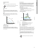
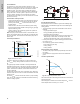
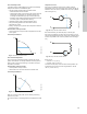
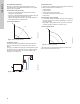
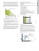
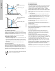
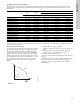

Table Of Contents
- English (US)
- 1. Limited warranty
- 2. General information
- 3. Receiving the product
- 4. Installing the product
- 5. Starting up the product
- 6. Handling and storing the product
- 7. Product introduction
- 8. Control functions
- 9. Setting the product
- 10. Servicing the product
- 11. Fault finding the product
- 12. Technical data
- 13. Accessories
- 14. Disposing of the product
- Français (CA)
- 1. Garantie limitée
- 2. Informations générales
- 3. Réception du produit
- 4. Installation du produit
- 4.1 Lieu d'installation
- 4.2 Outils
- 4.3 Coquilles d'isolation
- 4.4 Installation mécanique
- 4.5 Positionnement du circulateur
- 4.6 Positions du boîtier de commande
- 4.7 Position de la tête du circulateur
- 4.8 Modification de la position du boîtier de commande
- 4.9 Installation électrique
- 4.10 Branchement du câble de l'alimentation électrique
- 5. Démarrage du produit
- 6. Manutention et stockage du produit
- 7. Introduction au produit
- 8. Fonctions de régulation
- 8.1 Aperçu rapide des modes de régulation
- 8.2 Modes de fonctionnement
- 8.3 Modes de régulation
- 8.4 Fonctionnalités supplémentaires pour les modes de régulation
- 8.5 Modes circulateurs multiples
- 8.6 Valeurs de réglage pour les modes de régulation
- 8.7 Précision de l'estimation du débit
- 8.8 Tableau de la précision du débit
- 8.9 Branchements externes
- 8.10 Priorité des réglages
- 8.11 Communication entrée et sortie
- 9. Réglage du produit
- 10. Maintenance du produit
- 11. Détection des défauts de fonctionnement du produit
- 12. Caractéristiques techniques
- 13. Accessoires
- 14. Mise au rebut du produit
- Español (MX)
- 1. Garantía limitada
- 2. Información general
- 3. Recepción del producto
- 4. Instalación del producto
- 5. Puesta en marcha del producto
- 6. Manejo y almacenamiento del producto
- 7. Introducción de producto
- 8. Funciones de control
- 8.1 Breve resumen de los modos de control
- 8.2 Modos de operación
- 8.3 Modos de control
- 8.4 Otras funciones de los modos de control
- 8.5 Modos multibomba
- 8.6 Ajustes de los modos de control
- 8.7 Precisión de la estimación del caudal
- 8.8 Tabla de precisión del caudal
- 8.9 Conexiones externas
- 8.10 Prioridad de los ajustes
- 8.11 Comunicación de entrada y salida
- 9. Ajuste del producto
- 10. Mantenimiento y servicio del producto
- 11. Búsqueda de fallas del producto
- 12. Datos técnicos
- 13. Accesorios
- 14. Eliminación del producto
- Appendix

English (US)
28
Fig. 37 Constant-pressure control with FLOW
LIMIT
Fig. 38 Constant curve with FLOW
LIMIT
8.4.2 Automatic night setback
A night setback system is often integrated into a building
management system (BMS), or as part of an equivalent electronic
control system, which has a built-in timer.
The feature is not beneficial in a room that has underfloor heating
because of the regulating inertia of the underfloor heating.
Characteristics and key benefits
• Automatic night setback lowers the room temperature at night,
which reduces heating costs.
• The pump automatically changes between normal duty and
night setback (duty at low demand) depending on the flow pipe
temperature.
• Once activated, the pump runs on the minimum curve.
Technical specifications
The pump automatically changes to night setback when the
built-in sensor registers a flow-pipe temperature drop of more
than 18 to 27 °F (10 to 15 °C) within approximately two hours.
The temperature drop must be at least 0.18 °F/min (0.1 °C/min).
Changeover to normal duty takes place without time lag when the
temperature has increased by approximately 18 °F (10 °C).
8.5 Multipump modes
8.5.1 Multipump function
The multipump function enables the control of single-head pumps
connected in parallel and twin-head pumps without the use of
external controllers. The pump is designed for multipump
connection via the wireless GENIair connection. The built-in
wireless GENIair module enables communication between pumps
and with Grundfos GO without the use of add-on modules. See
section 10. Servicing the product and section 13.1 Grundfos GO.
Pump system:
• Twin-head pump.
• Two single-head pumps connected in parallel. The pumps
must be of equal size and type. Each pump requires a check
valve in series with the pump.
A multipump system is set via a selected pump, i.e. the master
pump (first selected pump). The multipump functions are
described in the following sections.
Configuration of twin-head pumps is described in section
5.2 Twin-head pump.
For information about input and output communication in a
multipump system, see section 8.11.1 External connections in a
multipump system.
8.5.2 Alternating operation
Only one pump is operating at a time. The change from one pump
to the other depends on time or energy. If a pump fails, the other
pump will take over automatically.
8.5.3 Backup operation
One pump is operating continuously. The backup pump is
operating at intervals to prevent seizing up. If the duty pump
stops due to a fault, the backup pump will start automatically.
8.5.4 Cascade operation
Cascade operation ensures that the pump performance is
automatically adapted to the consumption by switching pumps on
or off. The system thus runs as energy-efficiently as possible with
a constant pressure and a limited number of pumps.
The slave pump will start when the master pump is running at
maximum or has a fault, and it will stop again when the master
pump is running below 50 %.
Cascade operation is available in constant speed and constant
pressure. You can with advantage choose a twin-head pump, as
the backup pump will start for a short period in peak-load
situations.
All pumps in operation will run at equal speed. Pump changeover
is automatic and depends on speed, operating hours and faults.
TM05 2444 0312TM05 2542 0412
You cannot enable automatic night setback when the
pump is in constant-curve mode.
H
Q
H
set
MJNJU
Normal
constant-pressure duty
point
FLOW
LIMIT
duty point
H
Q
MJNJU
Normal constant-curve
duty point
FLOW
LIMIT
duty point