
User Guide
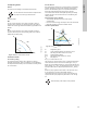
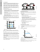
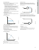
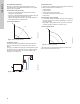
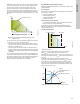
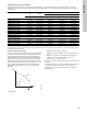
Table Of Contents
- English (US)
- 1. Limited warranty
- 2. General information
- 3. Receiving the product
- 4. Installing the product
- 5. Starting up the product
- 6. Handling and storing the product
- 7. Product introduction
- 8. Control functions
- 9. Setting the product
- 10. Servicing the product
- 11. Fault finding the product
- 12. Technical data
- 13. Accessories
- 14. Disposing of the product
- Français (CA)
- 1. Garantie limitée
- 2. Informations générales
- 3. Réception du produit
- 4. Installation du produit
- 4.1 Lieu d'installation
- 4.2 Outils
- 4.3 Coquilles d'isolation
- 4.4 Installation mécanique
- 4.5 Positionnement du circulateur
- 4.6 Positions du boîtier de commande
- 4.7 Position de la tête du circulateur
- 4.8 Modification de la position du boîtier de commande
- 4.9 Installation électrique
- 4.10 Branchement du câble de l'alimentation électrique
- 5. Démarrage du produit
- 6. Manutention et stockage du produit
- 7. Introduction au produit
- 8. Fonctions de régulation
- 8.1 Aperçu rapide des modes de régulation
- 8.2 Modes de fonctionnement
- 8.3 Modes de régulation
- 8.4 Fonctionnalités supplémentaires pour les modes de régulation
- 8.5 Modes circulateurs multiples
- 8.6 Valeurs de réglage pour les modes de régulation
- 8.7 Précision de l'estimation du débit
- 8.8 Tableau de la précision du débit
- 8.9 Branchements externes
- 8.10 Priorité des réglages
- 8.11 Communication entrée et sortie
- 9. Réglage du produit
- 10. Maintenance du produit
- 11. Détection des défauts de fonctionnement du produit
- 12. Caractéristiques techniques
- 13. Accessoires
- 14. Mise au rebut du produit
- Español (MX)
- 1. Garantía limitada
- 2. Información general
- 3. Recepción del producto
- 4. Instalación del producto
- 5. Puesta en marcha del producto
- 6. Manejo y almacenamiento del producto
- 7. Introducción de producto
- 8. Funciones de control
- 8.1 Breve resumen de los modos de control
- 8.2 Modos de operación
- 8.3 Modos de control
- 8.4 Otras funciones de los modos de control
- 8.5 Modos multibomba
- 8.6 Ajustes de los modos de control
- 8.7 Precisión de la estimación del caudal
- 8.8 Tabla de precisión del caudal
- 8.9 Conexiones externas
- 8.10 Prioridad de los ajustes
- 8.11 Comunicación de entrada y salida
- 9. Ajuste del producto
- 10. Mantenimiento y servicio del producto
- 11. Búsqueda de fallas del producto
- 12. Datos técnicos
- 13. Accesorios
- 14. Eliminación del producto
- Appendix

27
English (US)
Depending on the pump model, you can set the desired speed in
% of the maximum speed. The span of control depends on the
minimum speed, power and pressure limitation of the pump.
If the pump speed is set in the range between minimum and
maximum, the power and pressure are limited when the pump is
running on the maximum curve. This means that the maximum
performance can be achieved at a speed lower than 100 %. See
fig. 34.
Fig. 34 Power and pressure limitations influencing the
maximum curve
You can also set the pump to operate according to the maximum
or minimum curve, like an uncontrolled pump:
• You can use the maximum curve mode in periods in which a
maximum flow is required. This operating mode is for instance
suitable for hot-water priority.
• You can use the minimum curve mode in periods in which a
minimum flow is required. This operating mode is for instance
suitable for manual night setback if automatic night setback is
not desired.
You can select these two operating modes via the digital inputs.
In the control mode constant curve, you can obtain constant flow
by choosing a setpoint at 100 % and choosing the desired value
for the flow with the flow limit function FLOW
LIMIT
. Take the
accuracy of the flow estimation into consideration.
8.4 Additional control mode features
MAGNA3 offers additional features for the control modes to meet
specific demands.
8.4.1 FLOW
LIMIT
The feature is an integrated part of the FLOW
ADAPT
control mode,
but can also be used in:
• proportional-pressure mode
• constant-pressure mode
• constant-temperature mode
• constant-curve mode.
Characteristics and key benefits
• A control mode feature that, when activated, ensures that the
rated maximum flow is never exceeded.
By enabling FLOW
LIMIT
in systems where MAGNA3 has full
authority, the rated flow is never exceeded, thus eliminating the
need for throttling valves.
Technical specifications
Fig. 35 FLOW
LIMIT
The factory setting of the FLOW
LIMIT
is the flow where the
AUTO
ADAPT
factory setting meets the maximum curve.
The setting range for the FLOW
LIMIT
is 25 to 90 % of the Q
max
of
the pump. Do not set the FLOW
LIMIT
lower than the dimensioned
duty point.
In the flow range between 0 and Q
limit
, the pump will run
according to the selected control mode. When Q
limit
is reached,
the FLOW
LIMIT
function will reduce the pump speed to ensure
that the flow never exceeds the FLOW
LIMIT
set, no matter if the
system requires a higher flow due to increased resistance in the
system. See fig. 36, 37 or 38.
Fig. 36 Proportional-pressure control with FLOW
LIMIT
TM05 4266 2212
H
Q
Min.
30%
50%
70%
90%
Limited max. curve
Speed setting from 0 to 100 %
TM05 2445 1312TM05 2543 0412
H
Q
Q
max
Q
limit
90 %
Q
max
25 %
Setting range
H
Q
2
H
set
H
set
MJNJU
Normal
proportional-pressure
duty point
FLOW
LIMIT
duty point