
User Guide
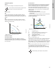
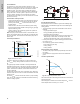
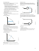
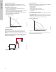
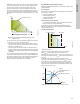
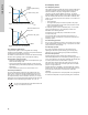
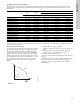
Table Of Contents
- English (US)
- 1. Limited warranty
- 2. General information
- 3. Receiving the product
- 4. Installing the product
- 5. Starting up the product
- 6. Handling and storing the product
- 7. Product introduction
- 8. Control functions
- 9. Setting the product
- 10. Servicing the product
- 11. Fault finding the product
- 12. Technical data
- 13. Accessories
- 14. Disposing of the product
- Français (CA)
- 1. Garantie limitée
- 2. Informations générales
- 3. Réception du produit
- 4. Installation du produit
- 4.1 Lieu d'installation
- 4.2 Outils
- 4.3 Coquilles d'isolation
- 4.4 Installation mécanique
- 4.5 Positionnement du circulateur
- 4.6 Positions du boîtier de commande
- 4.7 Position de la tête du circulateur
- 4.8 Modification de la position du boîtier de commande
- 4.9 Installation électrique
- 4.10 Branchement du câble de l'alimentation électrique
- 5. Démarrage du produit
- 6. Manutention et stockage du produit
- 7. Introduction au produit
- 8. Fonctions de régulation
- 8.1 Aperçu rapide des modes de régulation
- 8.2 Modes de fonctionnement
- 8.3 Modes de régulation
- 8.4 Fonctionnalités supplémentaires pour les modes de régulation
- 8.5 Modes circulateurs multiples
- 8.6 Valeurs de réglage pour les modes de régulation
- 8.7 Précision de l'estimation du débit
- 8.8 Tableau de la précision du débit
- 8.9 Branchements externes
- 8.10 Priorité des réglages
- 8.11 Communication entrée et sortie
- 9. Réglage du produit
- 10. Maintenance du produit
- 11. Détection des défauts de fonctionnement du produit
- 12. Caractéristiques techniques
- 13. Accessoires
- 14. Mise au rebut du produit
- Español (MX)
- 1. Garantía limitada
- 2. Información general
- 3. Recepción del producto
- 4. Instalación del producto
- 5. Puesta en marcha del producto
- 6. Manejo y almacenamiento del producto
- 7. Introducción de producto
- 8. Funciones de control
- 8.1 Breve resumen de los modos de control
- 8.2 Modos de operación
- 8.3 Modos de control
- 8.4 Otras funciones de los modos de control
- 8.5 Modos multibomba
- 8.6 Ajustes de los modos de control
- 8.7 Precisión de la estimación del caudal
- 8.8 Tabla de precisión del caudal
- 8.9 Conexiones externas
- 8.10 Prioridad de los ajustes
- 8.11 Comunicación de entrada y salida
- 9. Ajuste del producto
- 10. Mantenimiento y servicio del producto
- 11. Búsqueda de fallas del producto
- 12. Datos técnicos
- 13. Accesorios
- 14. Eliminación del producto
- Appendix

25
English (US)
8.3.5 Constant pressure
A constant pressure is advantageous in systems with relatively
small pressure losses in the distribution pipes:
• Two-pipe heating systems with thermostatic valves:
– dimensioned for natural circulation
– small pressure losses in those parts of the system where the
total quantity of water flows, for example a boiler, heat
exchanger and distribution pipe up to the first branching
– modified to a high differential temperature between flow pipe
and return pipe, for example district heating.
• Underfloor heating systems with thermostatic valves.
• One-pipe heating systems with thermostatic valves or
pipe-balancing valves.
• Primary circuit pumps in systems with small pressure losses in
the primary circuit.
Characteristics and key benefits
• The pump pressure is kept constant, independent of the flow
in the system.
Technical specifications
Fig. 27 Constant-pressure control
8.3.6 Constant temperature
This control mode is suitable in heating systems with a fixed
system characteristic, for example domestic hot-water systems,
where control of the pump according to a constant return-pipe
temperature is relevant.
Characteristics and key benefits
• The temperature is kept constant.
•Use FLOW
LIMIT
to control the maximum circulation flow.
Technical specifications
Fig. 28 Constant-temperature control
When you use this control mode, do not install any balancing
valves in the system.
The inverse control for cooling application is available from model
B.
Temperature sensor
If the pump is installed in the flow pipe, install an external
temperature sensor in the return pipe of the system. See fig. 29.
Install the sensor as close as possible to the consumer (radiator,
heat exchanger, etc.).
Fig. 29 Pump with an external sensor
We recommend that you install the pump in the flow pipe.
If the pump is installed in the return pipe of the system, you can
use the internal temperature sensor. In this case, install the pump
as close as possible to the consumer (radiator, heat exchanger,
etc.).
Fig. 30 Pump with the internal sensor
Sensor range:
• minimum +14 °F (-10 °C)
• maximum +266 °F (+130 °C)
To ensure that the pump is able to control the temperature, we
recommend that you set the sensor range between +23 and
+257 °F (-5 and +125 °C).
TM05 2449 0312TM05 2451 5111
H
Q
H
Q
TM05 2615 0312TM05 2616 0312
t
F
t
R
t
F
t
R