
User Guide
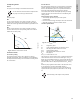
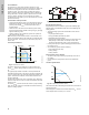
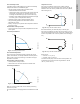
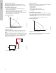
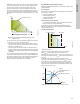
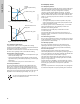
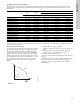

Table Of Contents
- English (US)
- 1. Limited warranty
- 2. General information
- 3. Receiving the product
- 4. Installing the product
- 5. Starting up the product
- 6. Handling and storing the product
- 7. Product introduction
- 8. Control functions
- 9. Setting the product
- 10. Servicing the product
- 11. Fault finding the product
- 12. Technical data
- 13. Accessories
- 14. Disposing of the product
- Français (CA)
- 1. Garantie limitée
- 2. Informations générales
- 3. Réception du produit
- 4. Installation du produit
- 4.1 Lieu d'installation
- 4.2 Outils
- 4.3 Coquilles d'isolation
- 4.4 Installation mécanique
- 4.5 Positionnement du circulateur
- 4.6 Positions du boîtier de commande
- 4.7 Position de la tête du circulateur
- 4.8 Modification de la position du boîtier de commande
- 4.9 Installation électrique
- 4.10 Branchement du câble de l'alimentation électrique
- 5. Démarrage du produit
- 6. Manutention et stockage du produit
- 7. Introduction au produit
- 8. Fonctions de régulation
- 8.1 Aperçu rapide des modes de régulation
- 8.2 Modes de fonctionnement
- 8.3 Modes de régulation
- 8.4 Fonctionnalités supplémentaires pour les modes de régulation
- 8.5 Modes circulateurs multiples
- 8.6 Valeurs de réglage pour les modes de régulation
- 8.7 Précision de l'estimation du débit
- 8.8 Tableau de la précision du débit
- 8.9 Branchements externes
- 8.10 Priorité des réglages
- 8.11 Communication entrée et sortie
- 9. Réglage du produit
- 10. Maintenance du produit
- 11. Détection des défauts de fonctionnement du produit
- 12. Caractéristiques techniques
- 13. Accessoires
- 14. Mise au rebut du produit
- Español (MX)
- 1. Garantía limitada
- 2. Información general
- 3. Recepción del producto
- 4. Instalación del producto
- 5. Puesta en marcha del producto
- 6. Manejo y almacenamiento del producto
- 7. Introducción de producto
- 8. Funciones de control
- 8.1 Breve resumen de los modos de control
- 8.2 Modos de operación
- 8.3 Modos de control
- 8.4 Otras funciones de los modos de control
- 8.5 Modos multibomba
- 8.6 Ajustes de los modos de control
- 8.7 Precisión de la estimación del caudal
- 8.8 Tabla de precisión del caudal
- 8.9 Conexiones externas
- 8.10 Prioridad de los ajustes
- 8.11 Comunicación de entrada y salida
- 9. Ajuste del producto
- 10. Mantenimiento y servicio del producto
- 11. Búsqueda de fallas del producto
- 12. Datos técnicos
- 13. Accesorios
- 14. Eliminación del producto
- Appendix

English (US)
24
8.3.3 FLOW
ADAPT
The FLOW
ADAPT
control mode combines AUTO
ADAPT
and
FLOW
LIMIT
, meaning that the pump runs AUTO
ADAPT
while at the
same time ensuring that the flow never exceeds the entered
FLOW
LIMIT
value. This control mode is suitable for systems
where a maximum flow limit is desired and where a steady flow
through the boiler in a boiler system is required. Here, no extra
energy is used for pumping too much liquid into the system.
In systems with mixing loops, you can use FLOW
ADAPT
to control
the flow in each loop.
Characteristics and key benefits
• The dimensioned flow for each zone (required heat energy) is
determined by the flow from the pump. This flow can be set
precisely in the FLOW
ADAPT
control mode without using
throttling valves.
• When the flow is set lower than the balancing valve setting,
the pump will ramp down instead of losing energy by pumping
against a balancing valve.
• Cooling surfaces in air-conditioning systems can operate at
high pressure and low flow.
Note: The pump cannot reduce the flow on the inlet side, but is
able to control that the flow on the outlet side is at least the same
as on the inlet side. This is due to the fact that the pump has no
built-in valve.
Technical specifications
Fig. 24 FLOW
ADAPT
control
The factory setting of the FLOW
ADAPT
is the flow where the
AUTO
ADAPT
factory setting meets the maximum curve. See fig.
24.
The typical pump selection is based on the required flow and
calculated pressure losses. The pump is typically oversized by 30
to 40 % to ensure that it can overcome the pressure losses in the
system. Under these conditions, the full benefit of AUTO
ADAPT
cannot be obtained.
To adjust the maximum flow of this "oversized" pump, balancing
valves are built into the circuit to increase the resistance and thus
reduce the flow.
The FLOW
ADAPT
function reduces the need for a pump throttling
valve, see fig. 25, but does not eliminate the need for balancing
valves in heating systems.
Fig. 25 Reduced need for a pump throttling valve
8.3.4 Proportional pressure
Proportional pressure is suitable in systems with relatively large
pressure losses in the distribution pipes and in air-conditioning and
cooling systems:
• Two-pipe heating systems with thermostatic valves and the
following:
– very long distribution pipes
– strongly throttled pipe-balancing valves
– differential-pressure regulators
– large pressure losses in those parts of the system where the
total quantity of water flows, for example a boiler, heat
exchanger and distribution pipe up to the first branching.
• Primary circuit pumps in systems with large pressure losses in
the primary circuit.
• Air-conditioning systems with the following:
– heat exchangers (fan coils)
– cooling ceilings
– cooling surfaces.
Characteristics and key benefits
• The head of the pump increases proportionally to the flow in
the system.
• Compensates for large pressure losses in the distribution
pipes.
Technical specifications
Fig. 26 Proportional-pressure control
The head is reduced at decreasing flow demand and increased at
rising flow demand.
The head against a closed valve is half the setpoint H
set
. You can
set the setpoint with an accuracy of 0.1 metre.
TM05 3334 1312
H
Q
Q
max
90 %
Q
max
25 %
H
auto_min
H
fac
Q
fac
Setting range
TM05 2685 1212TM05 2448 1212
H
Q
H
set
H
set
2