
User Guide
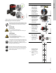
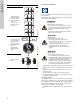
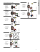
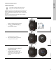
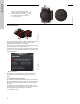
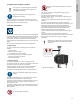
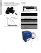
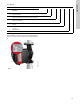
Table Of Contents
- English (US)
- 1. Limited warranty
- 2. General information
- 3. Receiving the product
- 4. Installing the product
- 5. Starting up the product
- 6. Handling and storing the product
- 7. Product introduction
- 8. Control functions
- 9. Setting the product
- 10. Servicing the product
- 11. Fault finding the product
- 12. Technical data
- 13. Accessories
- 14. Disposing of the product
- Français (CA)
- 1. Garantie limitée
- 2. Informations générales
- 3. Réception du produit
- 4. Installation du produit
- 4.1 Lieu d'installation
- 4.2 Outils
- 4.3 Coquilles d'isolation
- 4.4 Installation mécanique
- 4.5 Positionnement du circulateur
- 4.6 Positions du boîtier de commande
- 4.7 Position de la tête du circulateur
- 4.8 Modification de la position du boîtier de commande
- 4.9 Installation électrique
- 4.10 Branchement du câble de l'alimentation électrique
- 5. Démarrage du produit
- 6. Manutention et stockage du produit
- 7. Introduction au produit
- 8. Fonctions de régulation
- 8.1 Aperçu rapide des modes de régulation
- 8.2 Modes de fonctionnement
- 8.3 Modes de régulation
- 8.4 Fonctionnalités supplémentaires pour les modes de régulation
- 8.5 Modes circulateurs multiples
- 8.6 Valeurs de réglage pour les modes de régulation
- 8.7 Précision de l'estimation du débit
- 8.8 Tableau de la précision du débit
- 8.9 Branchements externes
- 8.10 Priorité des réglages
- 8.11 Communication entrée et sortie
- 9. Réglage du produit
- 10. Maintenance du produit
- 11. Détection des défauts de fonctionnement du produit
- 12. Caractéristiques techniques
- 13. Accessoires
- 14. Mise au rebut du produit
- Español (MX)
- 1. Garantía limitada
- 2. Información general
- 3. Recepción del producto
- 4. Instalación del producto
- 5. Puesta en marcha del producto
- 6. Manejo y almacenamiento del producto
- 7. Introducción de producto
- 8. Funciones de control
- 8.1 Breve resumen de los modos de control
- 8.2 Modos de operación
- 8.3 Modos de control
- 8.4 Otras funciones de los modos de control
- 8.5 Modos multibomba
- 8.6 Ajustes de los modos de control
- 8.7 Precisión de la estimación del caudal
- 8.8 Tabla de precisión del caudal
- 8.9 Conexiones externas
- 8.10 Prioridad de los ajustes
- 8.11 Comunicación de entrada y salida
- 9. Ajuste del producto
- 10. Mantenimiento y servicio del producto
- 11. Búsqueda de fallas del producto
- 12. Datos técnicos
- 13. Accesorios
- 14. Eliminación del producto
- Appendix

11
English (US)
Fig. 11 Fitting the pump head to the pump housing
4.8 Changing the control box position
TM05 5837 3216
The warning symbol on the clamp holding the pump
head and pump housing together indicates that there
is a risk of personal injury. See specific warnings
below.
CAUTION
Crushing of feet
Minor or moderate personal injury
- Do not drop the pump head when loosening the
clamp.
CAUTION
Pressurized system
Minor or moderate personal injury
- Pay special attention to any escaping vapor
when loosening the clamp.
Fit and tighten the screw that holds the clamp to 6 ±
0.7 ft-lbs (8 ± 1 Nm). Do not apply more torque than
specified even though water is dripping from the
clamp. The condensation is most likely coming from
the drain hole under the clamp.
Check the position of the clamp before you tighten
the clamp. Incorrect position of the clamp will cause
leakage from the pump and damage the hydraulic
parts in the pump head.
8Nm!
Step Action Illustration
1
Loosen the screw
in the clamp that
holds the pump
head and pump
housing together.
If you loosen the
screw too much,
the pump head will
be completely
disconnected from
the pump housing.
TM05 2867 3216
2
Carefully turn the
pump head to the
desired position.
If the pump head is
stuck, loosen it with
a light blow of a
rubber mallet.
TM05 2868 3216
3
Place the control
box in horizontal
position so that the
Grundfos logo is in
vertical position.
The motor shaft
must be in
horizontal position.
TM05 2869 3216
4
Due to the drain
hole in the stator
housing, position
the gap of the
clamp as shown in
step 4a or 4b.
TM05 2870 0612
4a
Single-head pump.
Position the clamp
so that the gap
points towards the
arrow.
It can be in position
3, 6, 9 or 12
o'clock.
TM05 2918 3216
5.0