
User Guide

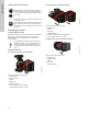
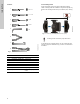
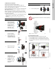
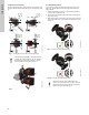
Table Of Contents
- English (US)
- 1. Limited warranty
- 2. General information
- 3. Receiving the product
- 4. Installing the product
- 5. Starting up the product
- 6. Handling and storing the product
- 7. Product introduction
- 8. Control functions
- 9. Setting the product
- 10. Servicing the product
- 11. Fault finding the product
- 12. Technical data
- 13. Accessories
- 14. Disposing of the product
- Français (CA)
- 1. Garantie limitée
- 2. Informations générales
- 3. Réception du produit
- 4. Installation du produit
- 4.1 Lieu d'installation
- 4.2 Outils
- 4.3 Coquilles d'isolation
- 4.4 Installation mécanique
- 4.5 Positionnement du circulateur
- 4.6 Positions du boîtier de commande
- 4.7 Position de la tête du circulateur
- 4.8 Modification de la position du boîtier de commande
- 4.9 Installation électrique
- 4.10 Branchement du câble de l'alimentation électrique
- 5. Démarrage du produit
- 6. Manutention et stockage du produit
- 7. Introduction au produit
- 8. Fonctions de régulation
- 8.1 Aperçu rapide des modes de régulation
- 8.2 Modes de fonctionnement
- 8.3 Modes de régulation
- 8.4 Fonctionnalités supplémentaires pour les modes de régulation
- 8.5 Modes circulateurs multiples
- 8.6 Valeurs de réglage pour les modes de régulation
- 8.7 Précision de l'estimation du débit
- 8.8 Tableau de la précision du débit
- 8.9 Branchements externes
- 8.10 Priorité des réglages
- 8.11 Communication entrée et sortie
- 9. Réglage du produit
- 10. Maintenance du produit
- 11. Détection des défauts de fonctionnement du produit
- 12. Caractéristiques techniques
- 13. Accessoires
- 14. Mise au rebut du produit
- Español (MX)
- 1. Garantía limitada
- 2. Información general
- 3. Recepción del producto
- 4. Instalación del producto
- 5. Puesta en marcha del producto
- 6. Manejo y almacenamiento del producto
- 7. Introducción de producto
- 8. Funciones de control
- 8.1 Breve resumen de los modos de control
- 8.2 Modos de operación
- 8.3 Modos de control
- 8.4 Otras funciones de los modos de control
- 8.5 Modos multibomba
- 8.6 Ajustes de los modos de control
- 8.7 Precisión de la estimación del caudal
- 8.8 Tabla de precisión del caudal
- 8.9 Conexiones externas
- 8.10 Prioridad de los ajustes
- 8.11 Comunicación de entrada y salida
- 9. Ajuste del producto
- 10. Mantenimiento y servicio del producto
- 11. Búsqueda de fallas del producto
- 12. Datos técnicos
- 13. Accesorios
- 14. Eliminación del producto
- Appendix

English (US)
10
4.6 Control box positions
To ensure adequate cooling, make sure that the control box is in
horizontal position with the Grundfos logo in vertical position. See
fig. 7.
Fig. 7 Pump with the control box in horizontal position
Fig. 8 Automatic vent
4.7 Pump head position
If you remove the pump head before installing the pump in the
pipes, pay special attention when fitting the pump head to the
pump housing:
1. Visually check that the floating ring in the sealing system is
centered. See figures 9 and 10.
2. Gently lower the pump head with rotor shaft and impeller into
the pump housing.
3. Make sure that the contact face of the pump housing and that
of the pump head are in contact before you tighten the clamp.
See fig. 11.
Fig. 9 Correctly centered sealing system
Fig. 10 Incorrectly centered sealing system
TM05 2915 3216
Twin-head pumps installed in horizontal pipes can
be fitted with an automatic vent, Rp 1/4" thread, in
the upper part of the pump housing if no venting
valve is installed in the system. See fig. 8.
TM05 6061 3216
TM05 6650 3216TM05 665132162
Observe the position of the clamp before you
tighten it. Incorrect position of the clamp will cause
leakage from the pump and damage the hydraulic
parts in the pump head. See fig. 11.