
MAGNA3 Installation Manual
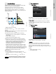
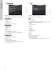
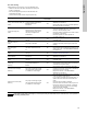
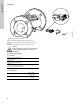
Table Of Contents
- English (US)
- 1. Limited warranty
- 2. Symbols used in this document
- 3. General information
- 4. Mechanical installation
- 5. Electrical installation
- 5.1 Supply voltage
- 5.2 Connection to the power supply (models 40-XX, 50-XX, 65-XX, 80-XX, 100-XX)
- 5.3 Connection to the power supply (models 32-XX)
- 5.4 Connection diagram
- 5.5 Input/output communication
- 5.6 Analog input for external sensor
- 5.7 Electrical connection for external sensor
- 5.8 Priority of settings
- 6. First start-up
- 7. Settings
- 8. Menu overview
- 9. Control panel
- 10. Menu structure
- 11. "Home" menu
- 12. "Status" menu
- 13. "Settings" menu
- 14. "Assist" menu
- 15. Selection of control mode
- 16. Fault finding
- 17. Sensor
- 18. Accessories
- 19. Technical data
- 20. Disposal
- Español (MX)
- 1. Garantía limitada
- 2. Símbolos utilizados en este documento
- 3. Información general
- 4. Instalación mecánica
- 5. Instalación eléctrica
- 5.1 Tensión de alimentación
- 5.2 Conexión al suministro eléctrico (modelos 40-XX, 50-XX, 65-XX, 80-XX y 100-XX)
- 5.3 Conexión al suministro eléctrico (modelos 32-XX)
- 5.4 Diagrama de conexiones
- 5.5 Comunicación de entrada/salida
- 5.6 Entrada analógica para sensor externo
- 5.7 Conexión eléctrica para sensor externo
- 5.8 Prioridad de los ajustes
- 6. Arranque inicial
- 7. Configurac.
- 8. Esquema de los menús
- 9. Panel de control
- 10. Estructura de los menús
- 11. Menú "Home"
- 12. Menú "Estado"
- 13. Menú "Configurac."
- 14. Menú "Assist"
- 15. Selección del modo de control
- 16. Localización de averías
- 17. Sensor
- 18. Accesorios
- 19. Datos técnicos
- 20. Eliminación
- Français (CA)
- 1. Garantie limitée
- 2. Symboles utilisés dans cette notice
- 3. Informations générales
- 4. Installation mécanique
- 5. Installation électrique
- 5.1 Tension d'alimentation
- 5.2 Branchement à l'alimentation électrique (modèles 40-XX, 50-XX, 65-XX, 80-XX, 100-XX)
- 5.3 Branchement à l'alimentation électrique (modèles 32-XX)
- 5.4 Diagramme de branchement
- 5.5 Communication entrée/sortie
- 5.6 Entrée analogique pour capteur externe
- 5.7 Branchement électrique pour capteur externe
- 5.8 Priorité des réglages
- 6. Première mise en marche
- 7. Réglages
- 8. Vue d'ensemble des menus
- 9. Panneau de commande
- 10. Structure des menus
- 11. Menu "Home"
- 12. Menu "Etat"
- 13. Menu "Réglages"
- 14. Menu "Assist"
- 15. Sélection du mode de régulation
- 16. Grille de dépannage
- 17. Capteur
- 18. Accessoires
- 19. Caractéristiques techniques
- 20. Mise au rebut

English (US)
38
16. Fault finding
16.1 Grundfos Eye operating indications
16.2 Signalling communication with remote control
The center indicator light in the Grundfos Eye will indicate communication with Grundfos GO Remote.
The table below describes the desired function of the center indicator light.
Warning
Before dismantling the pump, drain the system or close the isolating valve on either side of the pump.
The pumped liquid may be scalding hot and under high pressure.
Grundfos Eye Indication Cause
No lights on.
Power off.
Pump not running.
Two opposite green indicator lights running in the
direction of rotation of the pump.
Power on.
Pump running.
Two opposite green indicator lights permanently
on.
Power on.
Pump not running.
One yellow indicator light running in the direction
of rotation of the pump.
Warning.
Pump running.
One yellow indicator light permanently on.
Warning.
Pump stopped.
Two opposite red indicator lights flashing
simultaneously.
Alarm.
Pump stopped.
One green indicator light in the middle
permanently on (in addition to another
indication).
Remote-controlled.
The pump is currently being accessed by
Grundfos GO Remote.
Case Description Signalling by the center indicator light
Wink
The pump in question is highlighted in the Grundfos GO Remote display.
To inform the user of the location of the highlighted pump, the center
indicator light will flash four or five times once to signal "I am here".
Four or five quick flashes once to signal
"I am here".
Push me
The pump in question is selected/opened in the Grundfos GO Remote
menu. The pump will signal "Push me" to ask the user to select the
pump/allow the pump to exchange data with Grundfos GO Remote.
The indicator light will flash continuously until a pop-up window asks the
user to press [OK] to allow communication with Grundfos GO Remote.
Flashing continuously with 50 % duty
cycle.
I am connected
The indicator light is signalling that the pump is connected to Grundfos
GO Remote. The indicator light is permanently on as long as the pump is
selected in Grundfos GO Remote.
Indicator light permanently on.