
MAGNA3 Installation Manual
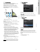
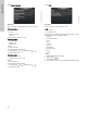
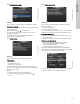
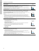
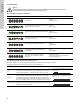
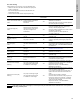
Table Of Contents
- English (US)
- 1. Limited warranty
- 2. Symbols used in this document
- 3. General information
- 4. Mechanical installation
- 5. Electrical installation
- 5.1 Supply voltage
- 5.2 Connection to the power supply (models 40-XX, 50-XX, 65-XX, 80-XX, 100-XX)
- 5.3 Connection to the power supply (models 32-XX)
- 5.4 Connection diagram
- 5.5 Input/output communication
- 5.6 Analog input for external sensor
- 5.7 Electrical connection for external sensor
- 5.8 Priority of settings
- 6. First start-up
- 7. Settings
- 8. Menu overview
- 9. Control panel
- 10. Menu structure
- 11. "Home" menu
- 12. "Status" menu
- 13. "Settings" menu
- 14. "Assist" menu
- 15. Selection of control mode
- 16. Fault finding
- 17. Sensor
- 18. Accessories
- 19. Technical data
- 20. Disposal
- Español (MX)
- 1. Garantía limitada
- 2. Símbolos utilizados en este documento
- 3. Información general
- 4. Instalación mecánica
- 5. Instalación eléctrica
- 5.1 Tensión de alimentación
- 5.2 Conexión al suministro eléctrico (modelos 40-XX, 50-XX, 65-XX, 80-XX y 100-XX)
- 5.3 Conexión al suministro eléctrico (modelos 32-XX)
- 5.4 Diagrama de conexiones
- 5.5 Comunicación de entrada/salida
- 5.6 Entrada analógica para sensor externo
- 5.7 Conexión eléctrica para sensor externo
- 5.8 Prioridad de los ajustes
- 6. Arranque inicial
- 7. Configurac.
- 8. Esquema de los menús
- 9. Panel de control
- 10. Estructura de los menús
- 11. Menú "Home"
- 12. Menú "Estado"
- 13. Menú "Configurac."
- 14. Menú "Assist"
- 15. Selección del modo de control
- 16. Localización de averías
- 17. Sensor
- 18. Accesorios
- 19. Datos técnicos
- 20. Eliminación
- Français (CA)
- 1. Garantie limitée
- 2. Symboles utilisés dans cette notice
- 3. Informations générales
- 4. Installation mécanique
- 5. Installation électrique
- 5.1 Tension d'alimentation
- 5.2 Branchement à l'alimentation électrique (modèles 40-XX, 50-XX, 65-XX, 80-XX, 100-XX)
- 5.3 Branchement à l'alimentation électrique (modèles 32-XX)
- 5.4 Diagramme de branchement
- 5.5 Communication entrée/sortie
- 5.6 Entrée analogique pour capteur externe
- 5.7 Branchement électrique pour capteur externe
- 5.8 Priorité des réglages
- 6. Première mise en marche
- 7. Réglages
- 8. Vue d'ensemble des menus
- 9. Panneau de commande
- 10. Structure des menus
- 11. Menu "Home"
- 12. Menu "Etat"
- 13. Menu "Réglages"
- 14. Menu "Assist"
- 15. Sélection du mode de régulation
- 16. Grille de dépannage
- 17. Capteur
- 18. Accessoires
- 19. Caractéristiques techniques
- 20. Mise au rebut

31
English (US)
13.7.2 Temperature influence
When this function is enabled in proportional- or
constant-pressure control mode, the setpoint for head will be
reduced according to the liquid temperature.
Temperature influence can be set to function at liquid
temperatures below +176 °F or +122 °F (80 °C or 50 °C).
These temperature limits are called T
max.
. The setpoint is
reduced in relation to the head set (= 100 %) according to the
characteristics below.
Fig. 38 Temperature influence
In the above example, T
max.
= +176 °F (+80 °C) has been
selected.
The actual liquid temperature T
actual
causes the setpoint for head
to be reduced from 100 % to H
actual
.
The temperature influence function requires the following:
• Proportional-pressure, constant-pressure or constant-curve
control mode.
• Pump installed in flow pipe.
• System with flow-pipe temperature control.
Temperature influence is suitable for the following systems:
• Systems with variable flows (for example two-pipe heating
systems) in which the enabling of the temperature influence
function will ensure a further reduction of the pump
performance in periods with small heating demands and
consequently a reduced flow-pipe temperature.
• Systems with almost constant flows (for example one-pipe
heating systems and underfloor heating systems), in which
variable heating demands cannot be registered as changes in
the head as is the case with two-pipe heating systems. In such
systems, the pump performance can only be adjusted by
enabling the temperature influence function.
Selection of T
max.
In systems with a dimensioned flow-pipe temperature of:
• up to and including +131 °F (+55 °C), select T
max.
= +122 °F
(+50 °C)
• above +131 °F (+55 °C), select T
max.
= +176 °F (80 °C).
13.8 Bus communication
13.8.1 Pump number
Navigation
Home > Settings > Bus communication > Pump number
Pump number
A unique number can be allocated to the pump. This makes it
possible to distinguish between pumps in connection with bus
communication.
13.9 General settings
13.9.1 Language
Navigation
Home > Settings > General settings > Language
Language
The display can be shown in any of the following languages:
GB, BG, CZ, DK, DE, EE, GR, ES, FR, HR, IT, LV, LT, HU, NL,
UA, PL, PT, RU, RO, SK, SI, RS, FI, SE, TR, CN, JP or KO.
Measuring units are automatically changed according to selected
language.
Setting:
1. Select language with and .
2. Press [OK] to enable.
TM05 7946 1613
Note
Note
The temperature influence function cannot be
used in air-conditioning and cooling systems.
H
T [°F]
30 %
68 122 176
T [°C]
20 50 80
100 %
H
actual
T
actual
H
Q
3.1.18.1.0.0 Pump number
TM05 7947 1613