
Install Instructions
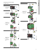
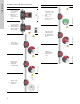
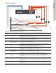

Table Of Contents
- English (US)
- 1. Limited warranty
- 2. Symbols used in this document
- 3. General information
- 4. Mechanical installation
- 5. Electrical installation
- 6. First start-up
- 7. Settings
- 8. Control panel
- 9. Overview of settings
- 10. Pump setting
- 11. Selection of control mode
- 12. Fault finding
- 13. Technical data
- 14. Disposal

11
English (US)
5.2 Connection to the power supply
5.2.1 Models 32-XX
Step Action Illustration
1
Remove the front
cover from the
control box.
TM06 1259 2014
2
Locate the power
supply plug inside
the control box.
TM06 1260 2014
3
Connect the
conduit and feed
the power cable
through the
control box.
TM06 1261 2014TM06 1262 2014
4
Strip the wires as
illustrated and
connect the
conductors to the
power supply
plug.
TM06 1263 2014TM06 1264 2014
L (L1)
N (L2)
0.28 in. (7 mm)
0.79 in. (20 mm)
0.28 in. (7 mm)
1.0 in. (25 mm)
Min.
ĭ0.28 in. (7 mm)
MaxĭPP
5
Insert the supply
plug into the
power receptacle
on the PCB.
TM06 1265 2014TM06 1266 2014
6
Tighten the
conduit and refit
the front cover.
TM06 1267 2014TM06 1268 2014
Step Action Illustration