GRUNDFOS INSTRUCTIONS MAGNA1 Installation and operating instructions
English (US) English (US) Installation and operating instructions 1. Limited warranty Original installation and operating instructions. CONTENTS Page 1. Limited warranty 2 2. Symbols used in this document 3 3. 3.1 3.2 3.3 3.4 3.5 3.6 3.7 3.8 3.9 General information Applications Pumped liquids Operating conditions Frost protection Insulating shells Non-return valve Wiring diagram Nameplate Tools 3 3 3 4 4 4 4 5 6 6 4. 4.1 4.2 4.3 4.4 4.
Warning If these safety instructions are not observed, it may result in personal injury. 3.2 Pumped liquids The pump is suitable for thin, clean, non-aggressive and nonexplosive liquids, not containing solid particles or fibers that may attack the pump mechanically or chemically. In heating systems, the water should meet the requirements of accepted standards on water quality in heating systems. Warning 3.2.
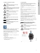
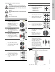
Insulating shells are available for single-head pumps only. Note Min./Max. 1 +14 °F to 230 °F 2 3 4 • Insulating shbells for pumps in heating systems are supplied with the pump. • For pumps in air-conditioning and cooling systems (down to 14 °F (-10 °C)) it is required to apply a silicon sealant to the internal contours of the shell in order to eliminate any air gaps and prevent condensation between the insulation shell and pump housing.
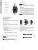
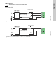
Caution English (US) 3.7 Wiring diagram All cables must be connected in accordance with local regulations. 3.7.1 For models 32-XX External switch GFCI Fuse TM06 1256 2214 (min. 10 A, time lag) Fig. 5 Example of terminal connection, 1 x 230 V ± 10 %, 50/60 Hz 3.7.2 For models 40-XX, 50-XX, 65-XX, 80-XX, 100-XX External switch GFCI Fuse TM03 2397 0312 (min. 10 A, time lag) Fig.
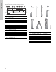
3.9 Tools The pump nameplate provides the following information: 1.2 x 8.0 TYPE 2 BOITIER DE TYPE 2 THERMALLY PROTECTED Nonsubmersible Pump For use with maximum 230° F water RISK OF ELECTRIC SHOCK. DE-ENERGIZE EQUIPMENT BEFORE REMOVAL OF COVER & SERVICING. FOR SUPPLY CONNECTION USE COPPER WIRE SUITABLE FOR 90 °C OR EQUIVALENT. THIS PUMP HAS NOT BEEN INVESTIGATED FOR USE IN SWIMMING POOL OR MARINE AREAS.
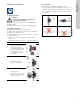
4.3 Positioning Always install the pump with horizontal motor shaft. 4.1 Lifting the pump • Pump installed correctly in a vertical pipe. See fig. 9, pos. A. • Pump installed correctly in a horizontal pipe. See fig. 9, pos. B. • Do not install the pump with vertical motor shaft. See fig. 9, pos. C and D. A B C D Warning Observe local regulations setting limits for manual lifting or handling. Always lift directly on the pump head or the cooling fins when handling the pump.
Fig. 10 Pump with control box in horizontal position If the pump head is removed before the pump is installed in the pipework, pay special attention when fitting the pump head to the pump housing: 1. Gently lower the pump head with rotor shaft and impeller into the pump housing. 2. Make sure that the contact face of the pump housing and that of the pump head are in contact before the clamp is tightened. See fig. 11. Fig.
When loosening the clamp, do not drop the pump head. Warning Risk of escaping vapor. 4 4a TM05 2867 0612 Carefully rotate the pump head to the desired position. If the pump head is stuck, loosen it with a light blow of a rubber mallet. TM05 5526 3812 Due to the drain hole in the stator housing, position the gap of the clamp as shown in step 4a, 4b, 4c, or 4d. Flanged single-head pump. Position the clamp so that the gap points towards the arrow. It can be in position 3 or 9 o'clock.
English (US) 5. Electrical installation Carry out the electrical connection and protection according to local regulations. Check that the supply voltage and frequency correspond to the values stated on the nameplate. Warning Switch off the power supply before making connections. Warning Never make any connections in the pump control box unless the power supply has been switched off for at least 5 minutes.
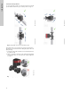
Step Action English (US) 5.2 Connection to the power supply Illustration 5.2.1 Models 32-XX 6 Tighten the conduit and refit the front cover. L (L1) N (L2) TM06 1265 2014 Insert the supply plug into the power receptacle on the PCB. TM06 1266 2014 3 Connect the conduit and feed the power cable through the control box. 5 TM06 1267 2014 Locate the power supply plug inside the control box. TM06 1262 2014 2 TM06 1259 2014 Remove the front cover from the control box.
8 Tighten the conduit adapter. Refit the front cover. 5 Strip the cable conductors as illustrated. TM05 5535 3812 7 Insert the power supply plug into the male plug in the pump control box. TM05 5537 3812 4 Pull the power supply cable through the conduit adapter. TM05 5533 3812 12 6 Connect the cable conductors to the power supply plug. L - L or L1 Ground - Ground N - N or L2 Connect the conduit adapter to the control box.
English (US) 6. First start-up Do not start the pump until the system has been filled with liquid and vented. Furthermore, the required minimum inlet pressure must be available at the pump inlet. See section 13. Technical data. The system cannot be vented through the pump. The pump is self-venting. Action 2 Control panel at first start-up. 3 The pump has been factoryset to the intermediate proportional-pressure curve. Select the control mode according to the system application.
Note If the pump impeller is rotated, for example when filling the pump with water, sufficient energy can be generated to light up the control panel even if the power supply has been switched off. 8.3 Light fields indicating the pump setting The pump has nine optional performance settings which can be selected with the push-button. See fig. 13, pos. 2 and 3. 8. Control panel The pump setting is indicated by nine light fields in the display.
English (US) 9. Overview of settings H PP3 CP3 PP2 CP2 PP1 II I TM05 2777 0512 CP1 III Q Fig. 15 Pump setting in relation to pump performance Setting Pump curve Function PP1 Lowest proportionalpressure curve The duty point of the pump will move up or down on the lowest proportional-pressure curve, depending on the heat demand. See fig. 15. The head (pressure) is reduced at falling heat demand and increased at rising heat demand.
Constant curve/constant speed (I, II or III) At constant-curve/constant-speed operation, the pump runs at a constant speed, independent of the actual flow demand in the system. The pump performance follows the selected performance curve, I, II or III. See fig. 19 where II has been selected. See section 11. Selection of control mode for further information. H Q TM05 5557 3812 Q TM05 5554 3812 H Fig. 19 Three constant-curve/constant-speed settings Fig.
System application In systems with relatively large pressure losses in the distribution pipes and in air-conditioning and cooling systems. • Two-pipe heating systems with thermostatic valves and – very long distribution pipes – strongly throttled pipe balancing valves – differential-pressure regulators – large pressure losses in those parts of the system through which the total quantity of water flows (for example boiler, heat exchanger and distribution pipe up to the first branching).
English (US) 12. Fault finding Warning Before dismantling the pump, drain the system or close the isolating valve on either side of the pump. The pumped liquid may be scalding hot and under high pressure. 12.1 Grundfos Eye operating status Grundfos Eye Indication Cause No lights on. Power off. Pump not running. Two opposite green indicator lights running in the direction of rotation of the pump. Power on. Pump running. Two opposite red indicator lights flashing simultaneously. Alarm. Pump stopped.
1 x 208-230 V ± 10 %, 50/60 Hz, PE. The relative minimum inlet pressures apply to pumps installed up to 984 ft (300 m), above sea level. For altitudes above 984 ft (300 m), the required relative inlet pressure must be increased by 0.145 psi / 0.01 bar / 0.001 MPa per 328 ft (100 m) altitude. The MAGNA1 pump is only approved for an altitude of 6561 ft (2000 m) above sea level. Motor protection EMC (electromagnetic compatibility) The pump requires no external motor protection.
GRUNDFOS Canada GRUNDFOS México 17100 West 118th Terrace Olathe, Kansas 66061 Phone: (913) 227-3400 Fax: (913) 227-3500 2941 Brighton Road Oakville, Ontario L6H 6C9 Canada Phone: +1-905 829 9533 Telefax: +1-905 829 9512 Boulevard TLC No. 15 Parque Industrial Stiva Aeropuerto C.P. 66600 Apodaca, N.L. México Phone: 011-52-81-8144 4000 Fax: 011-52-81-8144 4010 www.grundfos.us www.grundfos.ca www.grundfos.
98459387 0714 ECM: 1138863 www.grundfos.com www.grundfos.us The name Grundfos, the Grundfos logo, and be think innovate are registered trademarks owned by Grundfos Holding A/S or Grundfos A/S, Denmark. All rights reserved worldwide.