
Install Instructions
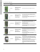
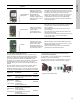
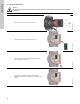
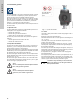
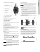
Table Of Contents
- English (US)
- 1. Limited warranty
- 2. Symbols used in this document
- 3. General information
- 4. Mechanical installation
- 5. Electrical installation
- 5.1 Supply voltage
- 5.2 Connection to the power supply (models 40-XX, 50-XX, 65-XX, 80-XX, 100-XX)
- 5.3 Connection to the power supply (models 32-XX)
- 5.4 Connection diagram
- 5.5 Input/output communication
- 5.6 Analog input for external sensor
- 5.7 Electrical connection for external sensor
- 5.8 Priority of settings
- 6. First start-up
- 7. Settings
- 8. Menu overview
- 9. Control panel
- 10. Menu structure
- 11. "Home" menu
- 12. "Status" menu
- 13. "Settings" menu
- 14. "Assist" menu
- 15. Selection of control mode
- 16. Fault finding
- 17. Sensor
- 18. Accessories
- 19. Technical data
- 20. Disposal
- Español (MX)
- 1. Garantía limitada
- 2. Símbolos utilizados en este documento
- 3. Información general
- 4. Instalación mecánica
- 5. Instalación eléctrica
- 5.1 Tensión de alimentación
- 5.2 Conexión al suministro eléctrico (modelos 40-XX, 50-XX, 65-XX, 80-XX y 100-XX)
- 5.3 Conexión al suministro eléctrico (modelos 32-XX)
- 5.4 Diagrama de conexiones
- 5.5 Comunicación de entrada/salida
- 5.6 Entrada analógica para sensor externo
- 5.7 Conexión eléctrica para sensor externo
- 5.8 Prioridad de los ajustes
- 6. Arranque inicial
- 7. Configurac.
- 8. Esquema de los menús
- 9. Panel de control
- 10. Estructura de los menús
- 11. Menú "Home"
- 12. Menú "Estado"
- 13. Menú "Configurac."
- 14. Menú "Assist"
- 15. Selección del modo de control
- 16. Localización de averías
- 17. Sensor
- 18. Accesorios
- 19. Datos técnicos
- 20. Eliminación
- Français (CA)
- 1. Garantie limitée
- 2. Symboles utilisés dans cette notice
- 3. Informations générales
- 4. Installation mécanique
- 5. Installation électrique
- 5.1 Tension d'alimentation
- 5.2 Branchement à l'alimentation électrique (modèles 40-XX, 50-XX, 65-XX, 80-XX, 100-XX)
- 5.3 Branchement à l'alimentation électrique (modèles 32-XX)
- 5.4 Diagramme de branchement
- 5.5 Communication entrée/sortie
- 5.6 Entrée analogique pour capteur externe
- 5.7 Branchement électrique pour capteur externe
- 5.8 Priorité des réglages
- 6. Première mise en marche
- 7. Réglages
- 8. Vue d'ensemble des menus
- 9. Panneau de commande
- 10. Structure des menus
- 11. Menu "Home"
- 12. Menu "Etat"
- 13. Menu "Réglages"
- 14. Menu "Assist"
- 15. Sélection du mode de régulation
- 16. Grille de dépannage
- 17. Capteur
- 18. Accessoires
- 19. Caractéristiques techniques
- 20. Mise au rebut

English (US)
44
18.3 Fitting the CIM module
Warning
Before fitting the module, switch off the power supply. Make sure that the power supply cannot be accidentally
switched on.
Step Action Illustration
1 Remove the front cover from the control box.
TM05 2875 0912
2 Fit the CIM module as illustrated and click it on.
TM05 2914 1112
3
Fit and tighten the screw holding the CIM module and
secure the earth connection.
TM05 2912 1112
4
For connection to fieldbus networks, see separate
installation and operating instructions for the desired CIM
module.
TM05 2913 1112