GRUNDFOS INSTRUCTIONS MAGNA Series 2000 MAGNA 32-60, 32-100 Installation and operating instructions 3191277 Conforms to ANSI/UL Std. 778 Certified to CAN/CSA Std.
(QJOLVK 86 English (US) Installation and operating instructions CONTENTS 1. Limited warranty Page 1. Limited warranty 2 2. Symbols used in this document 3 3. General description 3 4. 4.1 Applications Pumped liquids 3 3 5. 5.1 5.2 5.3 5.4 5.5 Installation Positioning Changing the control box position Insulation shells Non-return valve Frost protection 4 4 5 5 5 5 6. 6.1 6.2 Electrical connection Supply voltage Connection to the supply 6 6 6 7. Start-up 6 8. 8.1 8.2 6 6 8.3 8.4 8.
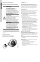
(QJOLVK 86 2. Symbols used in this document Warning &DXWLRQ If these safety instructions are not observed, it may result in malfunction or damage to the equipment! 1RWH Notes or instructions that make the job easier and ensure safe operation. TM04 9389 4010 If these safety instructions are not observed, it may result in personal injury! 3. General description Warning The use of this product requires experience with and knowledge of the product.
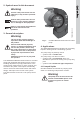
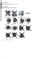
(QJOLVK 86 5. Installation Arrows on the pump housing indicate the liquid flow direction through the pump. 5.1 Positioning GRUNDFOS MAGNA must be installed with the pump head in horizontal position; see fig. 2. Fig.
.3 Insulation shells Warning 1RWH Before any dismantling of the pump, the system must be drained or the isolating valves on both sides of the pump must be closed as the pumped liquid may be scalding hot and under high pressure. Procedure: Turn the stator and the pump head to the desired position. 4 Push the stator and the pump head into place. TM04 9313 3910 Fig. 3 Shaded area indicates silicone RTV sealant 5.4 Non-return valve If a non-return valve is fitted in the pipe system, see fig.
7. Start-up The electrical connection and protection must be carried out in accordance with local regulations. Do not start the pump until the system has been filled with liquid and vented. Furthermore, the required minimum inlet pressure must be available at the pump inlet, see section 12. Technical data. The system cannot be vented through the pump. Warning Risk of electric shock — This pump is supplied with a grounding conductor and grounding-type attachment plug.
(QJOLVK 86 8.3 Functions selected via expansion modules Hmax. Further functions are available via the GENI module or the relay module: 8.3.2 Relay module • External start/stop The pump can be started and stopped via the digital input. • Fault, ready and operating indication via signal relay The pump controls an external fault, ready and operating signal relay via a potential-free output. The function of the signal relay is set with the R100. 8.
(QJOLVK 86 8.5 Selection of control mode Select this control mode System type Description Typical heating systems Grundfos recommends to let the pump remain in AUTOADAPT mode. This ensures optimum performance at the lowest possible energy consumption. 1.
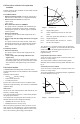
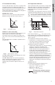
8.9 Temperature influence To be set with the R100, see section 9. Pump setup. The pump can be set to operate according to a constant curve, like an uncontrolled pump, see fig. 8. When the pump has been set to constant-curve mode with the R100, the setting can be changed on the control panel or with the R100. To be set with the R100, see section 9. Pump setup.
9. Pump setup The pump can be fitted with an expansion module enabling communication with external signals (signal transmitters). Two types of expansion modules are available: • Relay module • GENI module. For the setting of the pump, use: • control panel. • R100 remote control. • bus communication (not described in detail in these instructions, contact Grundfos). The table shows the application of the individual operating units and in which section the function has been described. Control panel R100 8.
Warning At high liquid temperatures, the pump may be so hot that only the buttons should be touched to avoid burns. 9.2.1 Control mode setting Description of function, see section 8.4 Control modes. To change the control mode, press , pos. 3, according to this cycle: (QJOLVK 86 9.2 Control panel The control panel, fig.
9.2.4 Setting to min. curve duty Description of function, see section 8.8 Max. or min. curve duty. To change over to the min. curve, press continuously until "MIN" illuminates, see fig. 15. To change back, press continuously until the desired setpoint is indicated. Fig. 13 Light fields MAGNA xx-100 9.2.3 Setting to max. curve duty Description of function, see section 8.8 Max. or min. curve duty. To change over to the max. curve, press continuously until "MAX" illuminates, see fig. 14.
The R100 displays are divided into four parallel menus, see fig. 16: 0. GENERAL, see operating instructions for R100 1. OPERATION 2. STATUS 3. INSTALLATION The number stated at each individual display in fig. 16 refers to the section in which the display is described. (QJOLVK 86 9.4 R100 display overview This display appears only once, i.e. when the R100 gets contact with the pump. 0. GENERAL 1. OPERATION 3. INSTALLATION 2. STATUS 9.5.1 9.6.1 9.7.1 9.5.2 9.6.2 9.7.2 9.5.3 9.6.3 9.7.3 9.5.
(QJOLVK 86 9.5 Menu OPERATION 9.5.3 Fault indications When the communication between the R100 and the pump has been established, "Contact with" appears in the display. When the "arrow down" on the R100 is pressed, menu OPERATION appears. 1RWH The display "Contact with" appears only once, i.e. when the R100 gets contact with the pump. 9.5.1 Setpoint This display depends on the control mode selected in the display "Control mode" in menu INSTALLATION.
9.6.7 Operating hours This display shows the actual operating mode (Stop, Min., Normal or Max.) and where it was selected (Pump, R100, BUS or External). Operating hours of the pump. The value of operating hours is an accumulated value and cannot be set to zero. 9.6.3 Head and flow (QJOLVK 86 9.6.2 Operating mode 9.7 Menu INSTALLATION This menu shows the settings that should be considered when installing the pump. 9.7.1 Control mode Description of function, see section 8.4 Control modes or 8.
(QJOLVK 86 1RWH If the pump is in control mode AUTO ADAPT or constant curve, the temperature influence cannot be set with the R100. The temperature influence function can be activated in this display when the control mode is proportional pressure or constant pressure; see section 9.7.1 Control mode. In the case of temperature influence, the pump must be installed in the flow pipe. It is possible to choose between maximum temperatures of 122 °F (50 °C) and 176 °F (80 °C). 9.7.
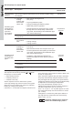
(QJOLVK 86 10. Troubleshooting Warning The pumped liquid may be scalding hot and under high pressure. Before any removal or dismantling of the pump, the system must therefore be drained or the isolating valves on either side of the pump must be closed. Indicator light is off. Indicator light is on. Indicator light is flashing. Indicator lights Green Fault Cause Remedy One fuse in the installation is blown/tripped out. Replace the fuse.
Green Fault Cause Remedy Red Noise in the system. Air in the system. Vent the system. The flow is too high. Reduce the setpoint and possibly change over to AUTOADAPT or constant pressure. The pressure is too high. Reduce the setpoint and possibly change over to AUTOADAPT or proportional pressure. The inlet pressure is too low. Increase the inlet pressure and/or check air volume in the expansion tank (if installed). Air in the pump.
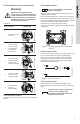
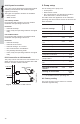
Megging of an installation incorporating a GRUNDFOS MAGNA pump is not allowed, as the built-in electronics may be damaged. If megging of the pump is necessary, the pump should be electrically separated from the installation. Warning Before removing the cables, the electricity must be switched off. Procedure: Megging of the pump Step Illustration Action • Switch off the electricity supply. • Open the connection box. TM03 0908 0705 1 L • Remove the supply wires L and N and the earth ground wire (GND).
(QJOLVK 86 12. Technical data Inputs and outputs of a pump with relay module Supply voltage 1 x 208 - 230 V +/- 10 %, 50/60 Hz. Motor protection The pump requires no external motor protection. Signal output Internal potential-free change-over contact. Maximum load: 250 V, 2 A, AC1. Minimum load: 5 V, 100 mA. Screened cable depending on signal level. Input for external start/stop External potential-free contact. Contact load: 5 V, 10 mA. Screened cable. Loop resistance: Maximum 130 :.
(QJOLVK 86 Master pump TM03 0857 0605 Master definition 21
TM03 0856 0605 (QJOLVK 86 Slave pump 22
Canada México GRUNDFOS Pumps Corporation 17100 West 118th Terrace Olathe, Kansas 66061 Phone: +1-913-227-3400 Telefax: +1-913-227-3500 GRUNDFOS Canada Inc. 2941 Brighton Road Oakville, Ontario L6H 6C9 Phone: +1-905-829-9533 Telefax: +1-905-829-9512 Bombas GRUNDFOS de México S.A. de C.V. Boulevard TLC No. 15 Parque Industrial Stiva Aeropuerto Apodaca, N.L.C.P. 66600 Phone: +52-81-8144-4000 Telefax: +52-81-8144-4010 *UXQGIRV FRPSDQLHV U.S.A.
Being responsible is our foundation Thinking ahead makes it possible Innovation is the essence L-MAG-TL-03 11.11 97758317 11.11 Repl. 10.11 US ECM: 1083640 © 2010 - 2011 Grundfos Pumps Corp. The name Grundfos, the Grundfos logo, and the payoff Be–Think–Innovate are registrated trademarks owned by Grundfos Management A/S or Grundfos A/S, Denmark. All rights reserved worldwide. www.grundfos.