
User Guide

3
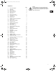
CONTENTS
Page
1. General description 4
2. Installation 4
2.1 Motor cooling 4
2.2 Outdoor installation 4
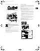
2.3 Electrical connection 4
2.4 Other connections 5
2.5 Signal cables 6
2.6 Bus connection cable 6
3. E-circulator series 1000 6
3.1 Control modes 6
3.2 Operating modes 6
3.3 Factory setting 6
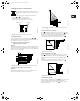
4. Setting by means of control panel 7
4.1 Setpoint setting 7
4.2 Setting to max. curve duty 7
4.3 Setting to min. curve duty 7
4.4 Start/stop of pump 7
5. Setting by means of R100 8
5.1 Menu OPERATION 9
5.2 Menu STATUS 9
5.3 Menu INSTALLATION 10
6. External forced-control signals 12
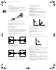
6.1 Start/stop input 12
6.2 Digital input 12
7. External setpoint signal 13
8. Bus signal 13
9. E-circulator series 2000 14
9.1 Functions 14
9.2 Operating modes 15
9.3 Factory setting 15
10. Setting the pump 15
11. Setting by means of control panel 15
11.1 Setting of pump head 15
11.2 Changeover between proportional pressure
and constant pressure 16
11.3 Setting to max. curve duty 16
11.4 Setting to min. curve duty 16
11.5 Start/stop of pump 16
12. Setting by means of R100 17
12.1 Menu OPERATION 18
12.2 Menu STATUS 18
12.3 Menu INSTALLATION 19
13. External forced-control signals 20
13.1 Start/stop input 20
13.2 Digital input 20
14. External setpoint signal 20
15. Bus signal 21
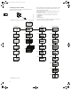
16. Priority of settings 21
17. Indicator lights and fault signal relay 22
18. Megging 22
19. Technical data 23
19.1 Supply voltage 23
19.2 Leakage current 23
19.3 Inputs/output 23
19.4 Other technical data 23
20. Disposal 23
21. Installation in the USA and Canada 24
21.1 Electrical installation 24
21.2 Before starting the pump 24
Warning
Prior to installation, read these installation and
operating instructions. Installation and operation
must comply with local regulations and accepted
codes of good practice.
Grundfos.bk Page 3 Thursday, November 11, 2010 11:21 PM