
User Guide

7
4. Setting by means of control panel
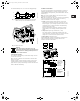
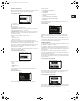
The pump control panel, fig. 10, incorporates the following:
• Buttons, and , for setpoint setting.
• Light fields, yellow, for indication of setpoint.
• Indicator lights, green (operation) and red (fault).
Fig. 10 Control panel for single-phase pumps
4.1 Setpoint setting
The desired setpoint is set by pressing the button or .
The light fields on the control panel will indicate the setpoint set.
See examples in sections 4.1.1 and 4.1.2.
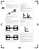
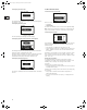
4.1.1 Pump in controlled-operation mode
(differential pressure control)
Example:
Figure 11 shows that the light fields 5 and 6 are activated, indicat-
ing a desired setpoint of 3.1 psi with a sensor measuring range
from 0 to 6 m. The setting range is equal to the sensor measuring
range (see sensor nameplate).
Fig. 11 Setpoint set to 3.1 psi (differential pressure control)
4.1.2 Pump in uncontrolled-operation mode
Example:
In uncontrolled-operation mode, the pump performance is set
within the range from min. to max. curve, fig. 12.
Fig. 12 Pump performance setting, uncontrolled-operation
mode
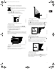
4.2 Setting to max. curve duty
Press continuously to change to the max. curve of the pump
(top light field flashes). When the top light field is on, must be
pressed for 3 seconds before the light field starts flashing.
To return to uncontrolled or controlled operation, press
continuously until the desired setpoint is indicated.
Fig. 13 Max. curve duty
4.3 Setting to min. curve duty
Press continuously to change to the min. curve of the pump
(bottom light field flashes). When the bottom light field is on,
must be pressed for 3 seconds before the light field starts
flashing.
To return to uncontrolled or controlled operation, press
continuously until the desired setpoint is indicated.
Fig. 14 Min. curve duty
4.4 Start/stop of pump
Stop the pump by continuously pressing until none of the light
fields are activated and the green indicator light flashes.
Start the pump by continuously pressing until the desired
setpoint is indicated.
At high system temperatures, the pump may be so
hot that only the buttons should be touched to avoid
burns.
TM00 7600 0304TM02 8987 1304
Indicator lights
Light fields
Buttons
5
4
3
2
1
0
Q
Q
H m
[psi]
TM00 7746 1304TM00 7345 1304TM00 7346 1304
H
Q
H
Q
H
Q
Grundfos.bk Page 7 Thursday, November 11, 2010 11:21 PM