
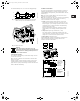
User Guide

5
For maximum backup fuse, see section 19.1 Supply voltage.
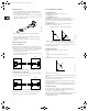
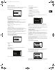
Fig. 2 Example of a mains-connected pump with mains
switch, back-up fuses and additional protection
Fig. 3 Mains connection
2.3.6 Start/stop of pump
The number of starts and stops via the mains voltage must not
exceed 4 times per hour.
When the pump is switched on via the mains, it will start after
approx. 5 seconds.
If a higher number of starts and stops is desired, the input for
external start/stop must be used when starting/stopping the
pump. When the pump is started/stopped via an external on/off
switch, it will start immediately.
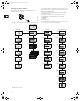
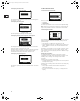
2.4 Other connections
The connection terminals of external potential-free contacts for
start/stop and digital function, external setpoint signal, sensor
signal, GENIbus, fault signal relay and communication cable are
shown in fig. 4.
Note: If no external on/off switch is connected, short-circuit
terminals 2 and 3 using a short wire.
Note: As a precaution, the wires to be connected to the following
connection groups must be separated from each other by
reinforced insulation in their entire lengths:
1. Inputs (external start/stop, digital function, setpoint and
sensor signals, terminals 1-9, and bus connection, B, Y, A).
All inputs (group 1) are internally separated from the mains-
conducting parts by reinforced insulation and galvanically
separated from other circuits.
All control terminals are supplied by protective extra-low
voltage (PELV), thus ensuring protection against electric
shock.
2. Output (fault signal relay, terminals NC, C, NO).
The output (group 2) is galvanically separated from other
circuits. Therefore, the supply voltage or protective extra-low
voltage can be connected to the output as desired.
3. Mains supply (terminals N, PE, L).
A galvanically safe separation must fulfill the requirements for
reinforced insulation including creepage distances and
clearances specified in EN 60 335.
Fig. 4 Connection terminals
TM02 0792 0101TM02 0827 1304
Warning
If the supply cable is damaged, it must be
replaced by the manufacturer, the manufacturer's
service partner or similarly qualified persons in
order to avoid a hazard.
N
PE
L
N
L
PE
ELCB
PE
L
N
TM02 0795 0904
0/1
10K
RUN
STOP
NC C NO N PE L
1987
65432
BYA
0-10 V
0/4-20 mA
4-20 mA
0/4-20 mA
0-10 V
Group 3
Group 1
1: Digital input
9: GND (frame)
8: +24 V
7: Sensor input
B: RS-485B
Y: Screen
A: RS-485A
6: GND (frame)
5: +10 V
4: Setpoint input
3: GND (frame)
2: Start/stop
Group 2
Grundfos.bk Page 5 Thursday, November 11, 2010 11:21 PM