
User Guide

4
1. General description
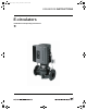
Grundfos E-Circulator pumps are pumps fitted with frequency-
controlled motors for single-phase mains connection.
The pumps are typically used as circulator pumps in large heating
or cooling water systems with variable demands.
The series 1000 pumps have a built-in PI controller and can be
connected to an external sensor enabling control of for instance
pressure, differential pressure, temperature, differential tempera-
ture or flow in the system in which the pumps are installed. The
pumps can also be set to uncontrolled operation, i.e. the pump
performance can be set according to an external control.
Series 1000 Pump: The desired value (setpoint), e.g. the desired
differential pressure if a differential pressure sensor has been
installed, can be set directly on the pump control panel, via an
input for external setpoint signal or by means of the Grundfos
wireless remote control R100.
The Series 2000 incorporate a PI controller and a differential
pressure sensor enabling control of the differential pressure
across the pump.
The series 2000 pump desired head can be set directly on the
pump control panel. At the same time, it is possible to choose
between two different control modes, i.e. proportional pressure
and constant pressure. The desired head can also be set via an
input for external setpoint signal or by means of the Grundfos
wireless remote control R100.
All other settings are made by means of the R100.
Important parameters such as actual value of control parameter,
power consumption, etc. can be read via the R100.
The pump incorporates
• inputs for external potential-free contacts for start/stop and
digital function. The digital function enables external setting to
max. curve or min. curve.
• an output for a potential-free fault signal.
• an input for bus communication.
Via the bus communication input, the pump can be controlled
and monitored by a GRUNDFOS Pump Management System
2000, a building management system or another external con-
trol system.
2. Installation
Note: In order to maintain the UL/cUL approval, additional instal-
lation procedures must be followed, see page 24.
2.1 Motor cooling
To ensure sufficient cooling of motor and electronics, the follow-
ing must be observed:
• Place the pump in such a way that sufficient cooling is
ensured.
• The temperature of the ambient air must not exceed 104°F.
• Cooling fins and fan blades must be kept clean.
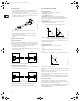
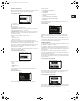
2.2 Outdoor installation
When installed outdoors, the pump must be provided with a suit-
able cover to avoid condensation on the electronic components,
fig. 1.
Fig. 1 Example of cover
For further installation, see installation and operating instructions
for the standard pump.
2.3 Electrical connection
Note: The user or the installer is responsible for the installation of
the correct earthing and protection according to valid national and
local standards. All operations must be carried out by a qualified
electrician.
2.3.1 Protection against electric shock – indirect contact
Protective earth conductors must always have a yellow/green
(PE) or yellow/green/blue (PEN) color marking.
2.3.2 Additional protection
If the pump is connected to an electric installation where an earth
leakage circuit breaker is used as additional protection, this
circuit breaker must be marked with the following symbol:
Note: When an earth leakage circuit breaker is selected, the total
leakage current of all the electrical equipment in the installation
must be taken into account.
The leakage current of the motor can be found in section
19.2 Leakage current.
2.3.3 Motor protection
The pump requires no external thermal motor protection. The
motor incorporates thermal protection against slow overloading
and blocking (IEC 34-11: TP 211).
2.3.4 Overvoltage protection
The pump is overvoltage-protected through built-in varistors
between phase-neutral and phase-earth.
2.3.5 Supply voltage
1 x 208-230v 60Hz PE.
The supply voltage and frequency are marked on the pump
nameplate. Please make sure that the motor is suitable for the
electricity supply on which it will be used.
The wires in the pump terminal box must be as short as possible.
Excepted from this is the protective earth conductor which must
be so long that it is the last one to be disconnected in case the
cable is inadvertently pulled out of the cable entry.
TM02 8514 0304
Warning!
All electric supply circuits must be interrupted
before working in the pump terminal box.
Warning
Never make any connections in the pump termi-
nal box unless the electricity supply has been
switched off for at least 5 minutes.
Warning
The pump must be earthed and protected against
indirect contact in accordance with local and
national regulations.
ELCB
Grundfos.bk Page 4 Thursday, November 11, 2010 11:21 PM