
User Guide

19
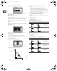
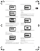
12.2.3 Display of actual value
The actually measured head will appear in this display.
12.2.4 Display of actual speed
Tolerance: ±5%
The actual pump speed will appear in this display.
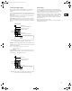
12.2.5 Display of input power and power consumption
Tolerance: ±10%
This display shows the actual pump input power from the mains
supply. The power is displayed in W or kW.
The pump power consumption can also be read from this display.
The value of power consumption is an accumulated value
calculated from the pump’s birth and it cannot be reset.
12.2.6 Display of operating hours
Tolerance: ±2%
The value of operating hours is an accumulated value and cannot
be reset.
12.3 Menu INSTALLATION
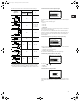
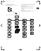
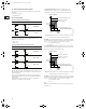
12.3.1 Selection of control mode
Select one of the following control modes (see fig. 20):
• Prop. pressure (proportional pressure),
• Const. pressure (constant pressure),
• Const. curve (constant curve).
The desired performance is set in section 12.1.1 Setpoint setting.
Note: If the pump is connected to a bus (see section 8. Bus sig-
nal), it is not possible to select the control mode via the R100.
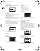
12.3.2 Selection of external setpoint signal
The input for external setpoint signal can be set to different signal
types. Select one of the following types:
• 0-10 V,
• 0-20 mA,
• 4-20 mA,
• Not active.
If Not active is selected, the setpoint set by means of the R100 or
on the control panel will apply.
The setpoint set is the maximum value of the external setpoint
signal, section 14. External setpoint signal. The actual value of
the external setpoint can be read from section 12.2.1 Display of
actual setpoint.
12.3.3 Blocking of the buttons on the pump
The buttons and on the pump can be set to:
• Active,
• Not active.
12.3.4 Allocation of pump number
A number between 1 and 64 can be allocated to the pump. In the
case of bus communication, a number must be allocated to each
pump.
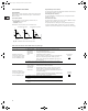
12.3.5 Selection of function for digital input
The digital input of the pump (terminal 1, fig. 4) can be set to
different functions.
Select one of the following functions:
• Min. (min. curve),
• Max. (max. curve).
The selected function is activated by closing the contact between
terminals 1 and 9 (fig. 4).
See also section 13.2 Digital input.
Min.:
When the input is activated, the pump is operating according to
the min. curve.
Grundfos.bk Page 19 Thursday, November 11, 2010 11:21 PM