
Install Instructions

7
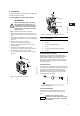
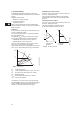
5.2 Connection diagram
Fig. 6 Wiring diagram
Concerning demands on signal wires and signal
transmitters, see section 11. Technical data.
A connection example can be found on page 49.
Note:
• If no external on/off switch is connected, the
connection across terminals STOP and should
be maintained.
• All cables used must be heat-resistant up to
+185 °F (+85 °C).
• All cables used must be installed in accordance
with NEC or applicable local codes and
regulations.
• If a GENI module is fitted, the screen must be
connected to . See page 50.
TM02 0235 1007
S
T
O
P
78
NC NO C
213
N
L
Supply connection Signal output Start/stop input
NC NO C
WARNING!
• Wires connected to
– supply terminals,
– outputs NC, NO, C and
– start/stop input
must be separated from each other
and from the supply by reinforced
insulation.
• All wires connected to a terminal
block must be tied up at the
terminals.